
Industry
Automation Robotics Cable Assemblies and Wire Harnesses
Automation and robotics cable assemblies and wire harnesses connect servos, encoders, PLCs, sensors, cabinets, and moving axes. Pinout, shield termination, grounding, travel, bend radius, and functional checks are the main build variables.
Request a QuoteServo, encoder, sensor, PLC, cabinet connections
- Servo motor, encoder, PLC cabinet, and machine interface cables
- Flexible or retractable cable assemblies where movement is specified
- Connectorized harnesses with labels, routing protection, and test steps
- Shielding and grounding plans for signal and control cables
Movement, bend radius, shielding, grounding
- High-flex or repeated-motion needs can affect material and construction
- Shielding schemes should show signal, grounding, and test expectations
- Connector substitutions may require project acknowledgement
- Industrial routing can involve oil, UV, temperature, or IP requirements
Application evidence
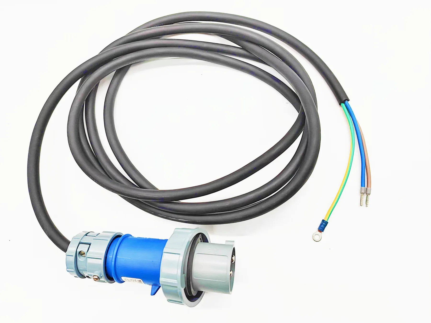
Visible assembly details to discuss
Use the visible connector, routing, branch, and cable-exit details to identify what the equipment drawing and inspection plan should control.
Application controls
Control points for the assembly
| Assembly interface | Cable type, conductor count, wire gauge, and bend radius |
|---|---|
| Routing and materials | Connector brand, model, pinout, and mating interface |
| Use conditions | Flexing, travel, shielding, grounding, and environmental requirements |
| Tests and records | Continuity, polarity, hi-pot, functional, or visual inspection criteria |
Verification
Testing and record inputs
- Check continuity, polarity, shield path, grounding, connector keying, and installed orientation.
- Keep motion or flex validation separate from routine production electrical checks.
- Record the assembly revision, setup, fixture or program, limits, results, and sample identity.
Before quotation
Common application questions
What defines an automation cable interface?
Control the connector part numbers and keying, pinout, shield and ground termination, cable exit, routing, motion profile, labels, and functional test.
When does movement need its own validation plan?
Define a motion profile when the cable repeatedly bends, twists, retracts, or travels with the equipment. Include bend radius, travel, duty, installation, environment, method, and acceptance criteria.
Related routes
Relevant products, capabilities, and guides
Request a quote
Send schematic, movement profile
Show the connector interfaces, cable route, shield and ground treatment, travel or bend conditions, and required functional checks.