
Capability
Cable Insert Overmolding
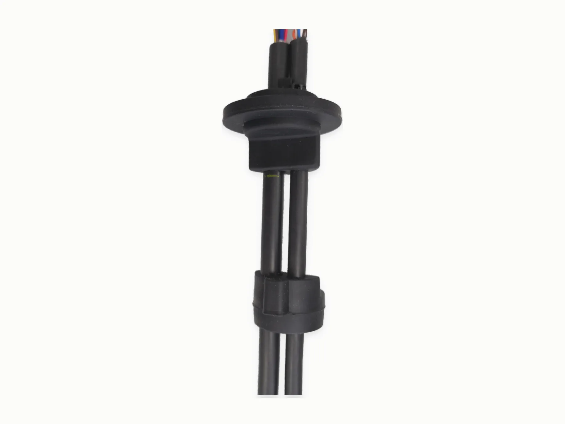
MTTJ uses vertical insert molding to add a protective shape around connector exits, breakouts, cable stops, glands, and junctions. The work covers insert preparation, molding, trimming, appearance checks, and electrical checks.
Request a Quote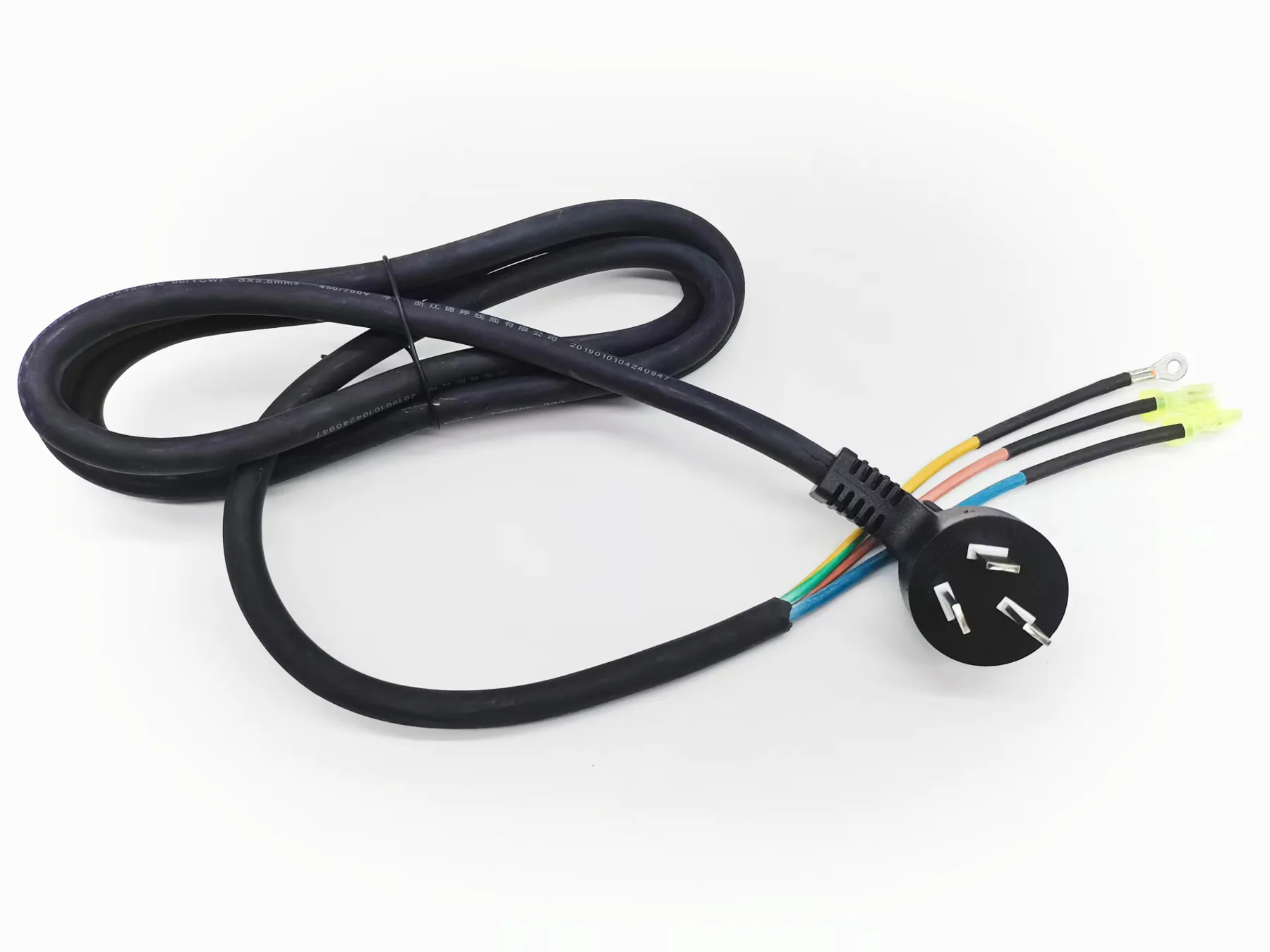
Geometry, material, tooling
- What connector or cable exit needs strain relief?
- Is the overmold geometry already specified in a drawing?
- Which material, hardness, color, or marking is required?
- Does the part need a gland, stop, breakout, Y junction, or T junction?
Dimensions needed for a tooling check
- Connector, cable, and molded geometry from drawing, sample, sketch, or 3D view
- Material hardness, color, marking, tooling need, and quantity
- Validation target for sealing, pull, mechanical, or electrical checks with method and pass/fail limits
Inspection
What is checked after molding
The molded envelope, cable exit, material, flash, surface, marking, and any specified sealing feature are checked against the drawing or reference sample.
| Geometry | Drawing, 3D model, sample, or sketch specifies molded shape and cable exit. |
|---|---|
| Material | PVC, PU / TPU, TPE, silicone, or another project-specified material is checked against the application and processing requirements. |
| Sealing | IP, airtightness, or waterproof targets are built around the requested level, fixture idea, and validation method. |
Process examples
Visible process details tied to RFQ inputs
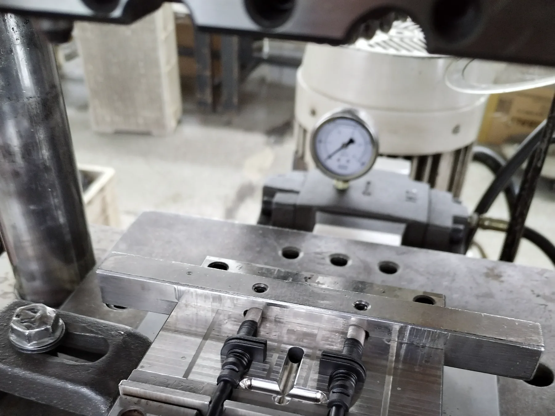
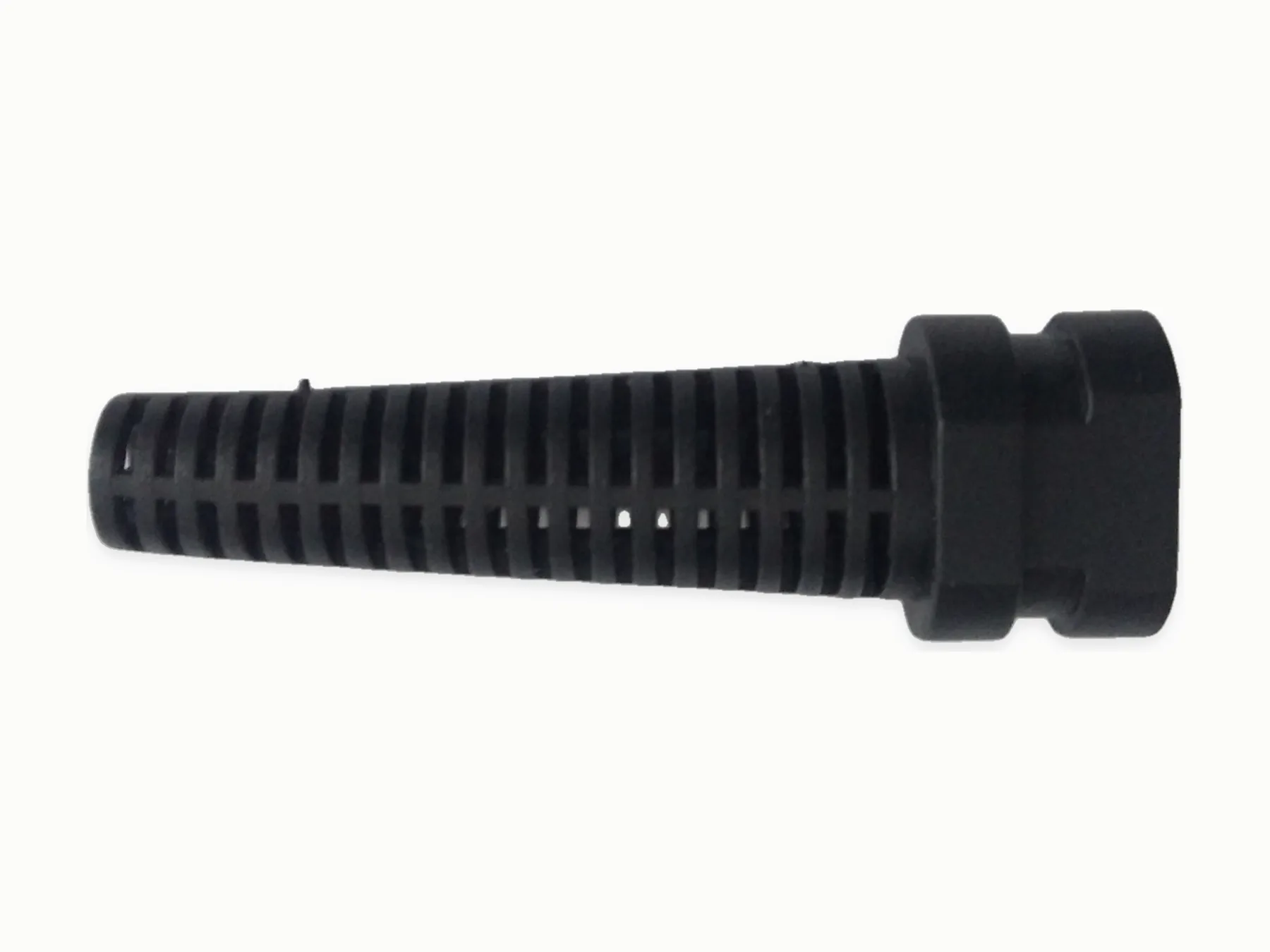
These images show where drawings, dimensions, connector details, materials, tests, and records affect the manufacturing step.
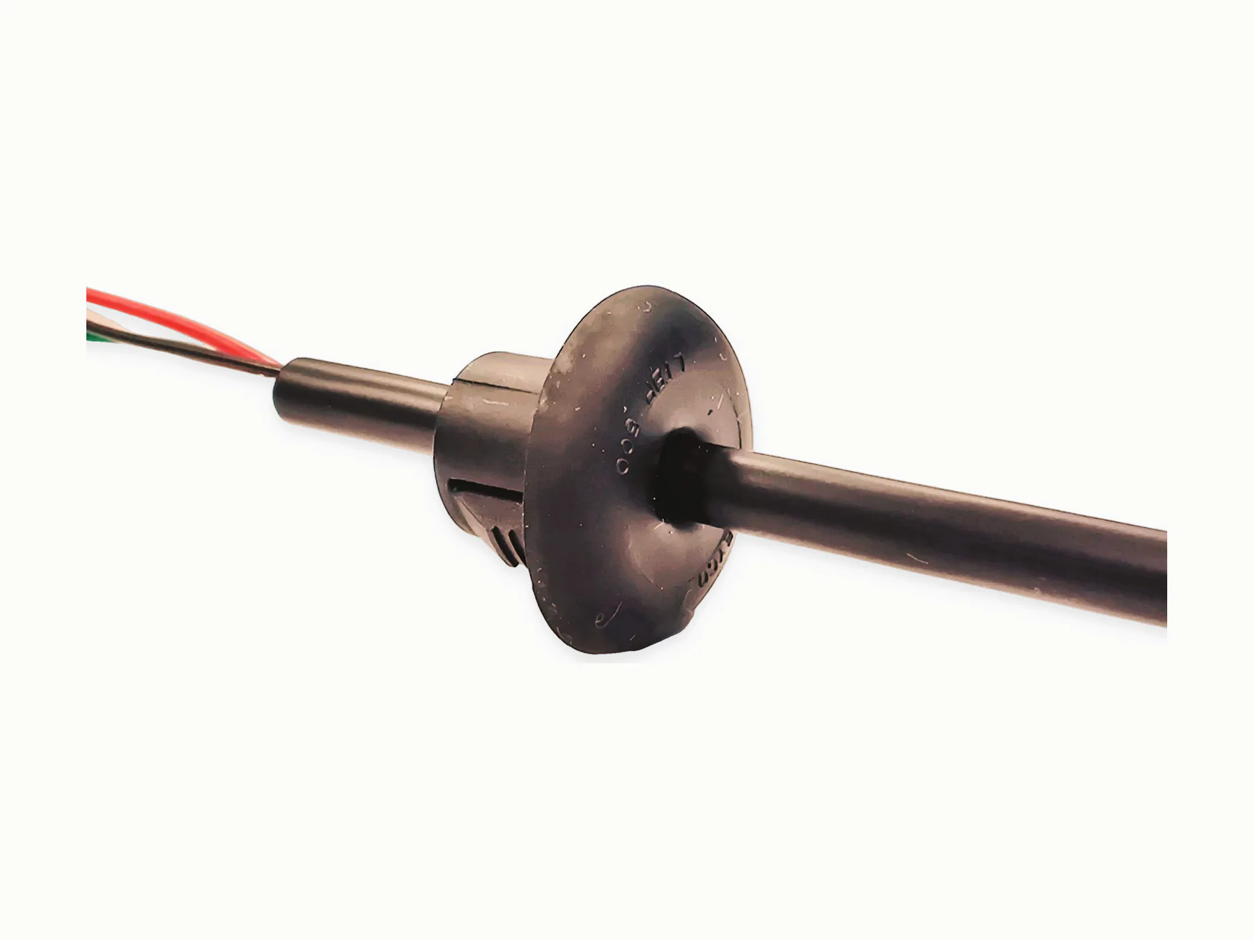
In‑house process
Insert molding in the Tianjin factory
Cable and connector preparation, insert loading, vertical molding, trimming, appearance checks, and electrical checks can be completed in-house.
- Vertical overmolding / insert molding
- Wire cutting
- Wire stripping
- Terminal crimping
- Soldering
- Electrical testing
Tooling and tests
New cavities, sealing targets, fixtures
A new cavity, unusual hardness, mixed cable diameters, sealing targets, or dedicated fixtures need separate engineering work before sampling.
Qualified-supplier coordination
- Horizontally injection-molded housings requiring horizontal molding machines
- PCB assemblies / circuit boards
- Specified plug, connector, or component sourcing
Process
From prepared insert to finished molded cable
The connectorized insert is loaded into the tool, molded, cooled, trimmed, and checked against the released geometry.
- 1Read the drawing, connector, cable, and application requirements
- 2List material preference, geometry, and tooling requirements
- 3Prepare cable and connector subassembly
- 4Run vertical insert molding or overmolding workflow when suitable
- 5Inspect molded geometry, run electrical tests
Related routes
Products using overmolding
Request a quote
Send the molded geometry
A drawing or 3D view should show the insert, cable exit, molded envelope, material, and any pull or sealing requirement.