
Solutions
Complex Cable Assembly and Wire Harness Projects
Some cable assemblies and wire harnesses combine cable preparation, crimping, soldering, overmolding, harness layout, labeling, testing, and export packing. Planning these operations from one drawing package reduces handoff errors and makes sample and production builds easier to compare.
Project examples
Build detail examples
The examples show cable routes, connector ends, molded features, and other assembly details used to align drawings, samples, tests, and required records for quotation and build planning.
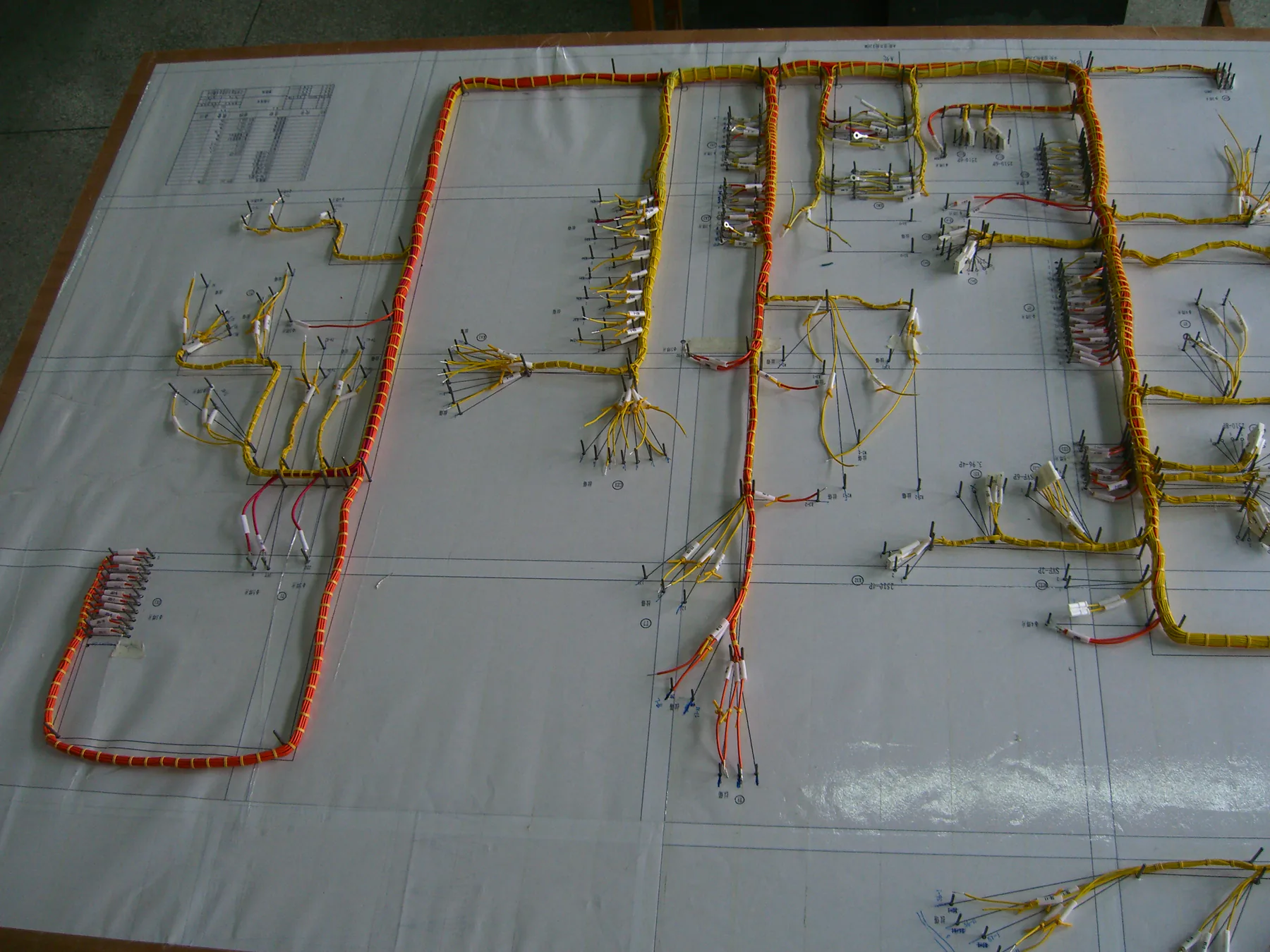
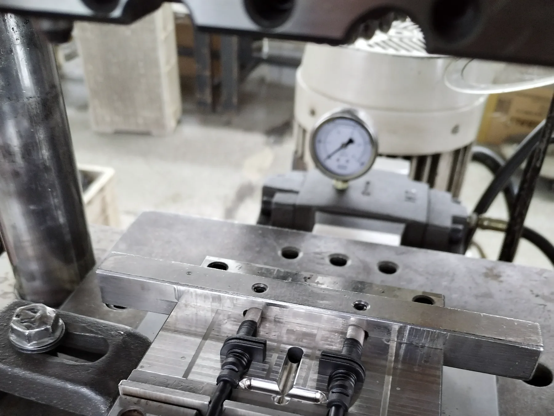
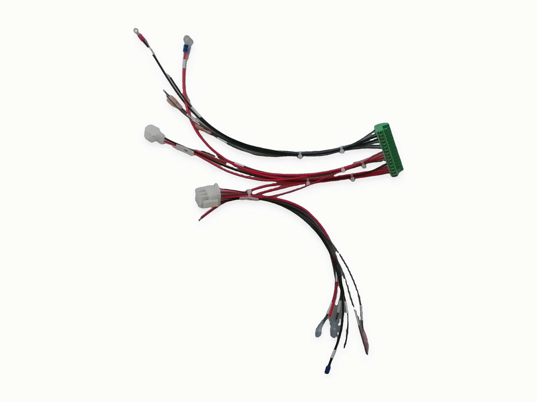
For assemblies that combine several manufacturing operations
- The assembly includes crimping, soldering, shielding, overmolding, and routing features
- Several connector types or branch lengths need to stay coordinated
- You need one inquiry package for manufacturing, testing, and delivery details
- The project may require both in-house process planning and component sourcing
Use one drawing, BOM, pinout, test criteria
- Assembly drawing, wiring table, pinout, and branch dimensions
- BOM, connector part numbers, wire or cable construction, and no-substitution notes
- Quantity, sample plan, required tests, records, labels, packing, and delivery destination
Process planning
Termination, molding, routing, testing alignment
- Process order for cutting, termination, molding, routing, packing, and shipment records
- Crimp, solder, shield handling, overmold, and assembly constraints
- Continuity, polarity, hi-pot, functional, or visual inspection requirements
Drawings and notes
Pinouts, molded geometry, routing, test evidence
- Assembly drawing, wiring table, pinout, and sample photos
- Photos of critical routing, exits, or mating equipment when available
- Test method, pass/fail criteria, and required record format
Related products
Related capabilities
Continue the review
Related resources and manufacturing scope
Project quotation
Keep the full assembly under one revision
FAQ
Multi-process cable assemblies
Can one assembly combine several manufacturing processes?
Yes. A single drawing package can cover cable preparation, termination, overmolding, harness layout, labeling, testing, and packing. The sequence and tooling are planned as one build.
What creates the most risk in complex assemblies?
Unclear pinout, branch length, connector selection, shielding, and test criteria can all change manufacturing steps, so they belong in the same inquiry package.
Request a quote
Send the complete assembly package
The drawing and BOM should connect termination, overmolding, branch layout, labels, tests, and packing without conflicting revisions.