
MTTJ Mold-Tech logo

Custom Cable & Molding

Custom Cable Constructions & Injection-Molded Components

MTTJ combines cable preparation, termination, insert molding, and injection-molded component work for custom constructions defined by a drawing or sample. The product range includes molded inserts, strain relief, cable exits, junctions, and finished cable assemblies.

Send Project Details
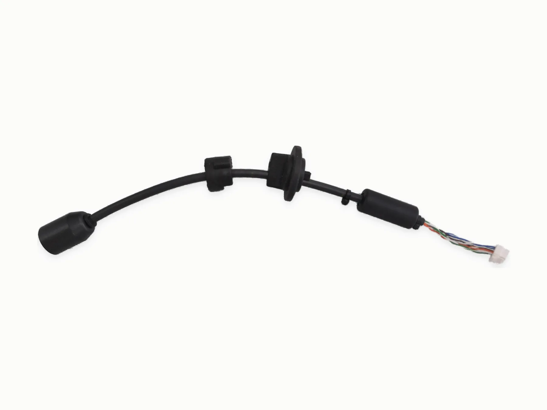
Black custom cable lead with molded component and prepared wire ends

Overmolded strain relief at a connector exit

The molded section controls the cable exit and spreads bending load away from the termination. The connector body and cable diameter also affect the tool cavity.

Connector exits, breakouts, cable stops

  • Industrial automation equipment
  • Commercial equipment controls
  • Security and electronic equipment
  • Sensor and probe cable assemblies
  • Custom interconnects requiring molded strain relief

Shape, hardness, color, marking

  • Connector strain relief
  • Cable breakouts
  • Y junctions and T junctions
  • Cable stops
  • Seals and glands when the drawing includes dimensions and a validation method
  • Custom color and marking

Molding compounds and cable compatibility

  • PVC
  • PU / TPU
  • TPE
  • TPEE
  • TPV
  • Silicone

Molded geometry

Draw the envelope before tooling is chosen

The drawing should show the connector, cable exit angle, molded envelope, cable diameter, and any sealing surfaces. Material hardness and marking can then be matched to the shape.

Overmold geometryDrawing, connector size, cable exit angle, and strain-relief length set the molded envelope.
Material hardnessFlexibility, sealing target, handling feel, and temperature exposure guide material hardness.
ToolingNew geometry may need prototype tooling before a production quote can be fixed.
Color and markingColor, logo, and marking details should appear on the drawing or marking note.
Environmental exposureMoisture, dust, flexing, vibration, and temperature exposure decide whether validation testing is needed.

Product range

Custom cable constructions and injection-molded components

The gallery combines finished cable constructions with molded component examples. Use the closest visible geometry to start a discussion about inserts, exits, junctions, materials, tooling, and inspection points.

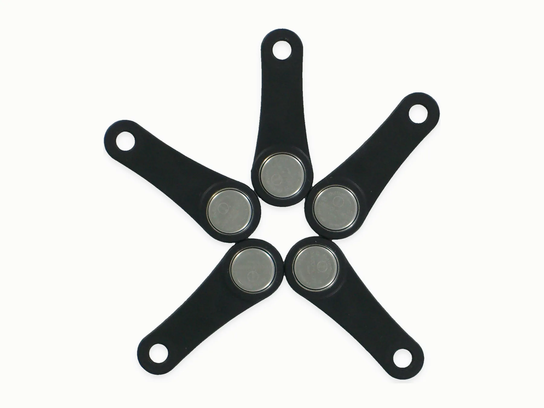
Four black molded arms with round metal inserts arranged as a matched component set.
Cable constructions and molded components

Four-arm molded component

Four black molded arms with round metal inserts arranged as a matched component set.

Market / context
Project-specific
Equipment end
Round metal inserts
Discuss this molded construction
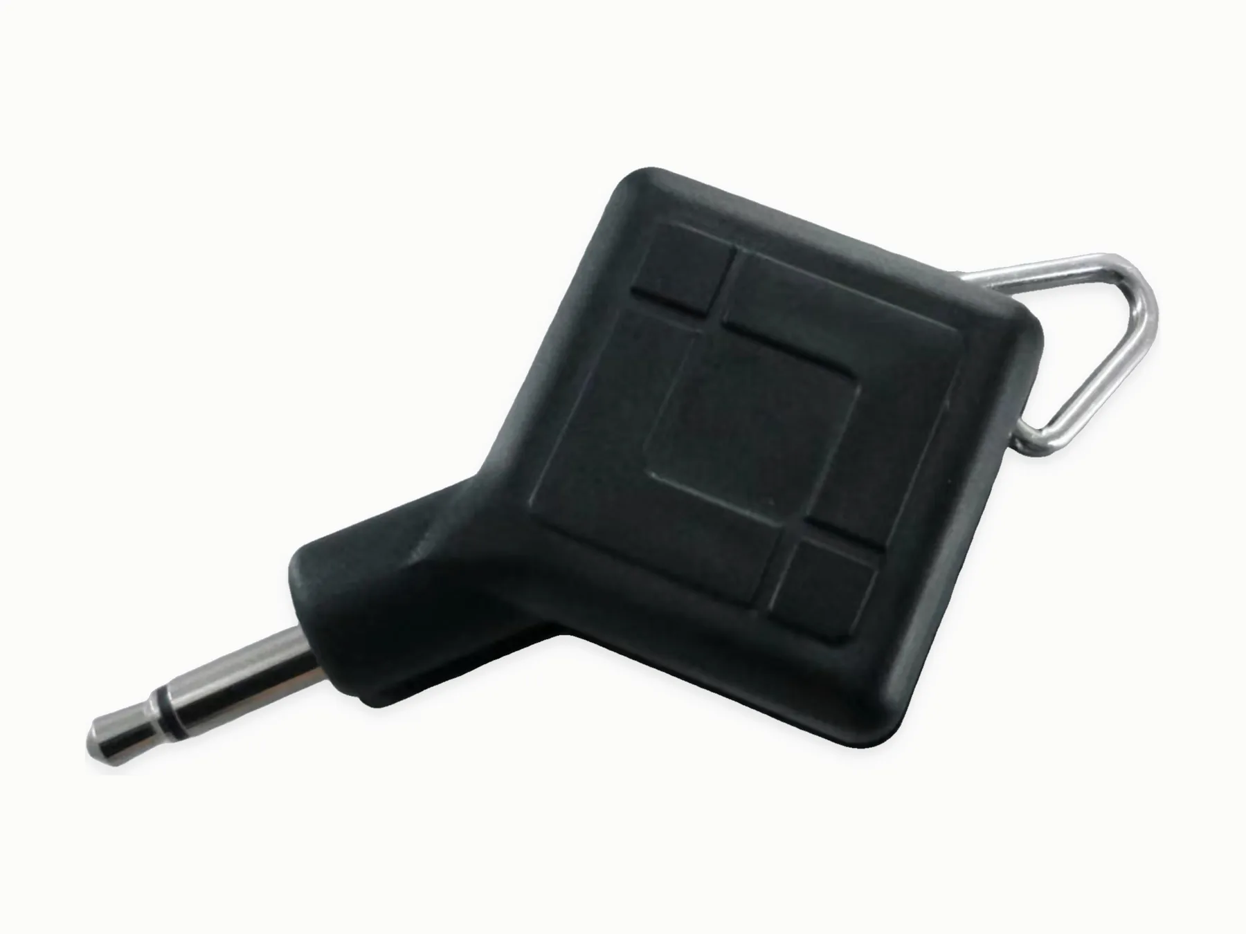
Black molded handle component with a metal shaft and loop for insert and envelope discussion.
Cable constructions and molded components

Molded handle component

Black molded handle component with a metal shaft and loop for insert and envelope discussion.

Market / context
Project-specific
Equipment end
Metal shaft and loop
Discuss this molded construction
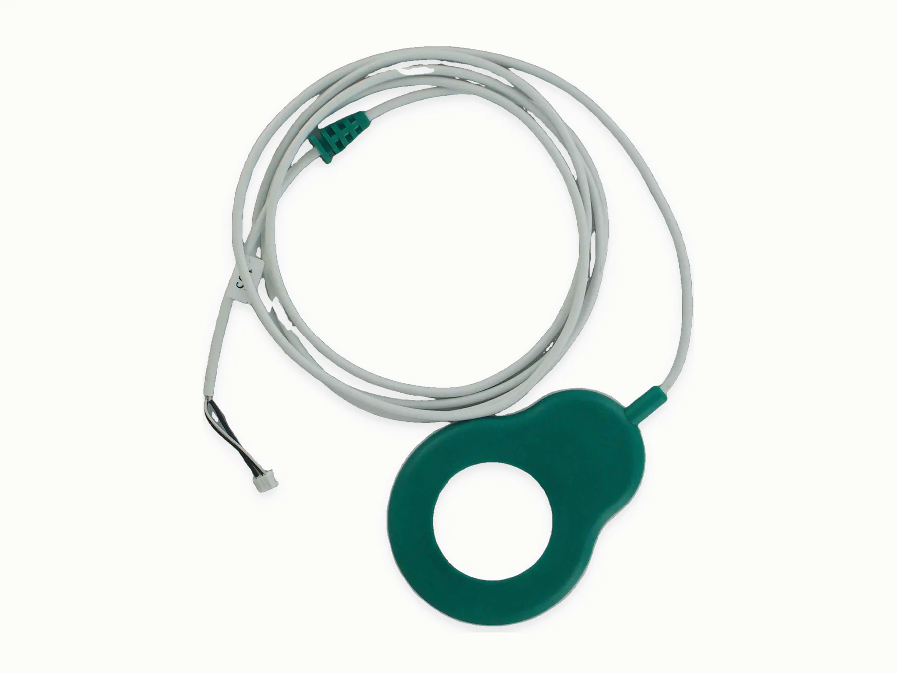
Gray cable assembly routed through a circular green component with prepared ends visible.
Cable constructions and molded components

Cable with molded ring component

Gray cable assembly routed through a circular green component with prepared ends visible.

Market / context
Project-specific
Equipment end
Prepared cable ends
Discuss this molded construction
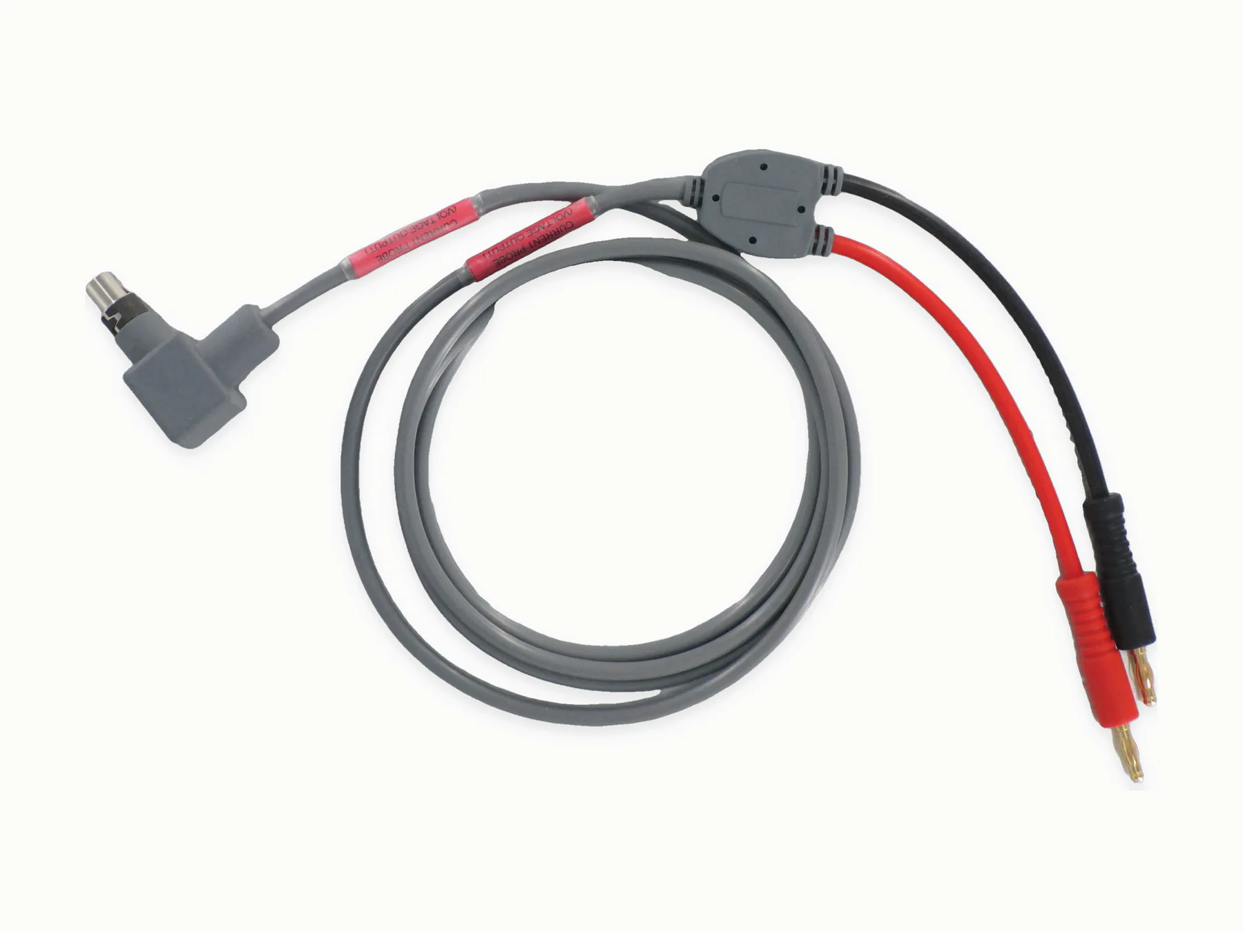
Gray and red cable leads meet at a black overmolded junction with several end styles visible.
Cable constructions and molded components

Dual-lead overmolded junction

Gray and red cable leads meet at a black overmolded junction with several end styles visible.

Market / context
Project-specific
Equipment end
Connectorized leads
Discuss this molded construction
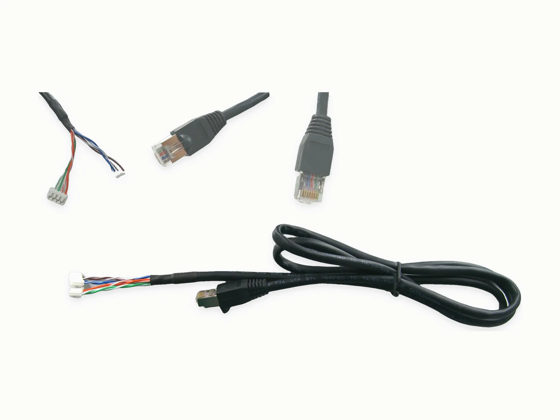
Cable sample set showing modular connector ends, molded reliefs, and prepared conductors.
Cable constructions and molded components

Modular connector sample set

Cable sample set showing modular connector ends, molded reliefs, and prepared conductors.

Market / context
Project-specific
Equipment end
Modular plugs and prepared conductors
Discuss this molded construction
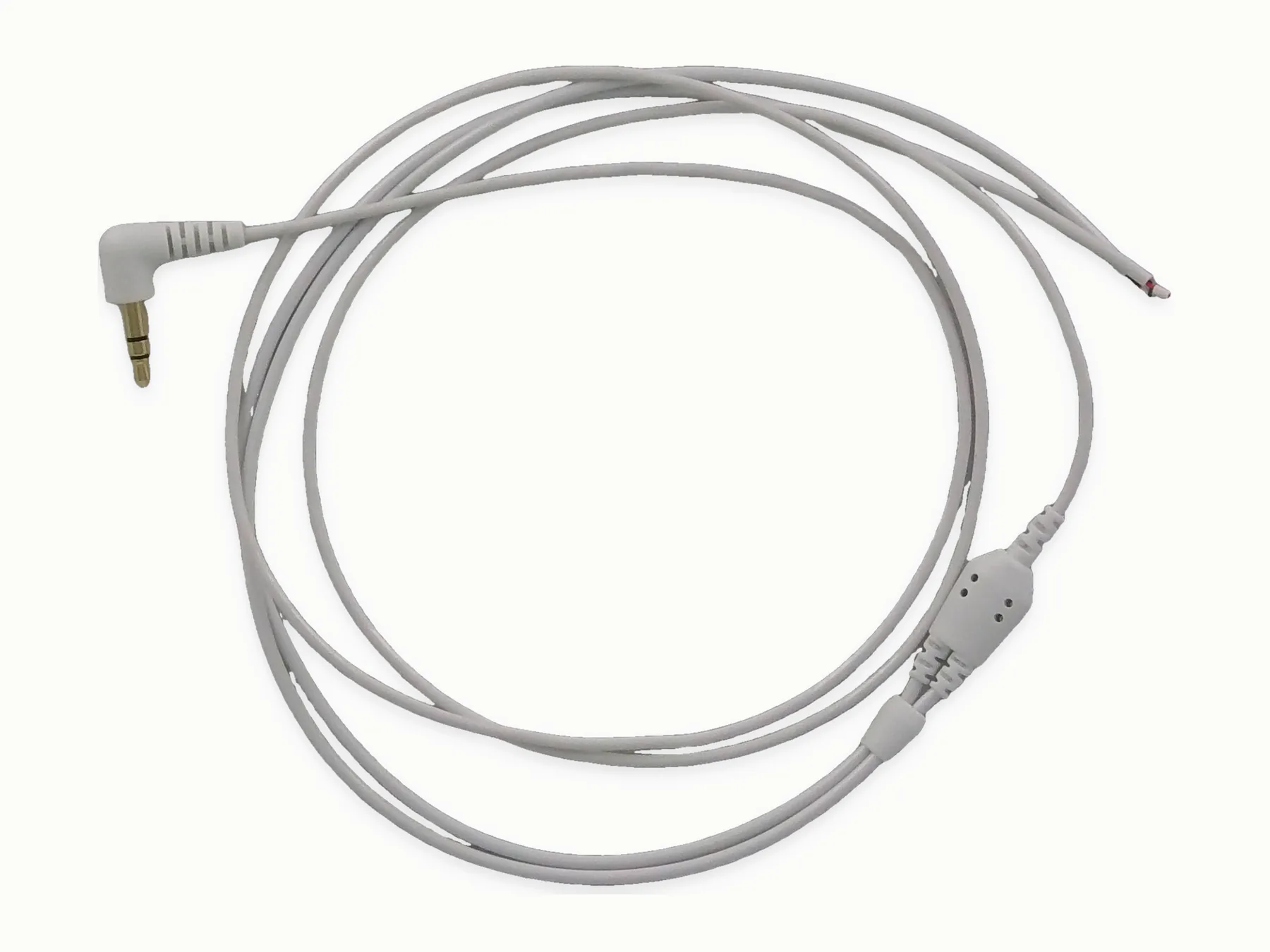
Gray cable lead with a right-angle audio plug, overmolded junction, and prepared wire ends.
Cable constructions and molded components

Audio lead with molded junction

Gray cable lead with a right-angle audio plug, overmolded junction, and prepared wire ends.

Market / context
Project-specific
Equipment end
Right-angle audio plug
Discuss this molded construction
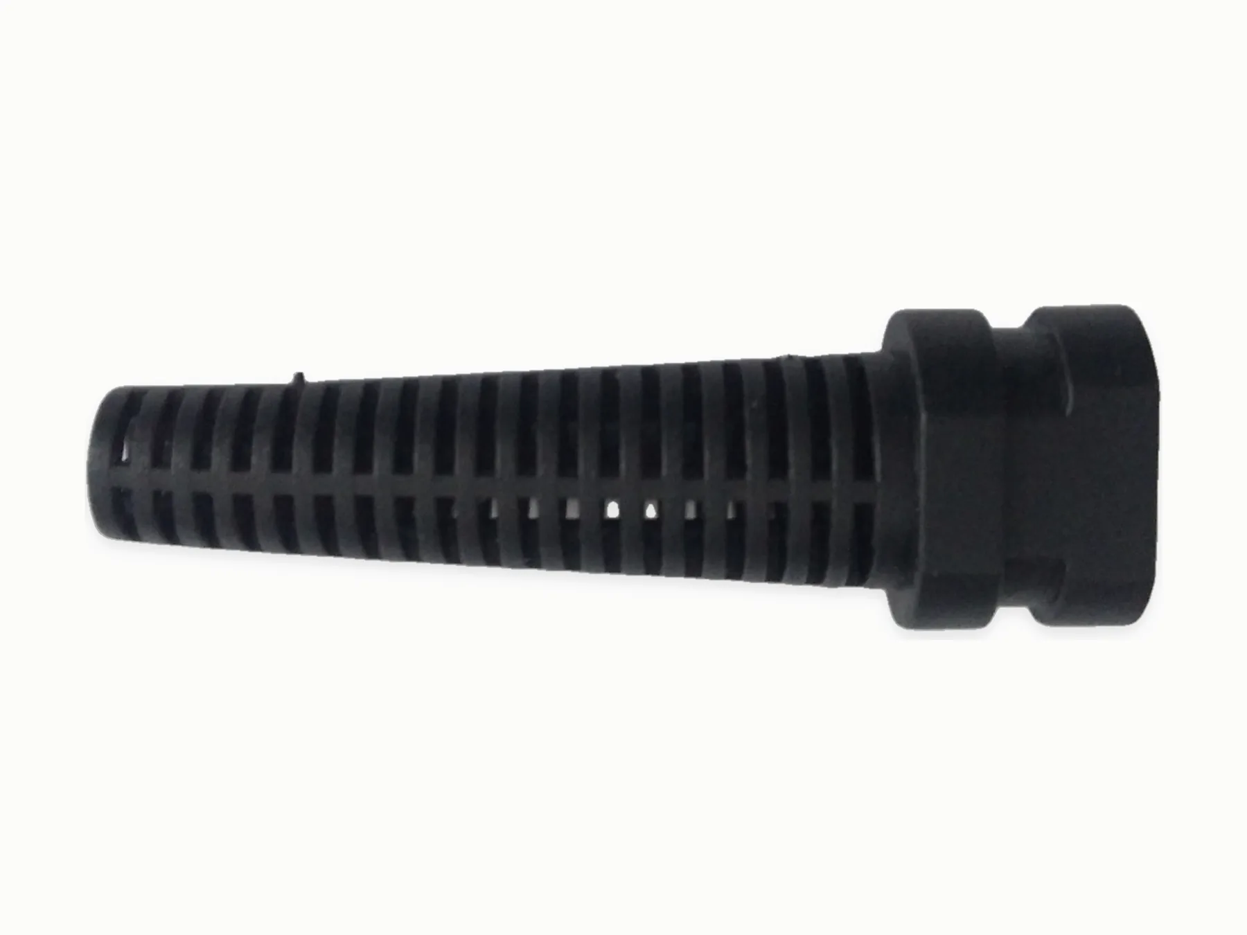
Black ribbed molded component showing the strain-relief profile and cable-exit geometry.
Cable constructions and molded components

Molded strain-relief component

Black ribbed molded component showing the strain-relief profile and cable-exit geometry.

Market / context
Project-specific
Equipment end
Cable exit boot
Discuss this molded construction
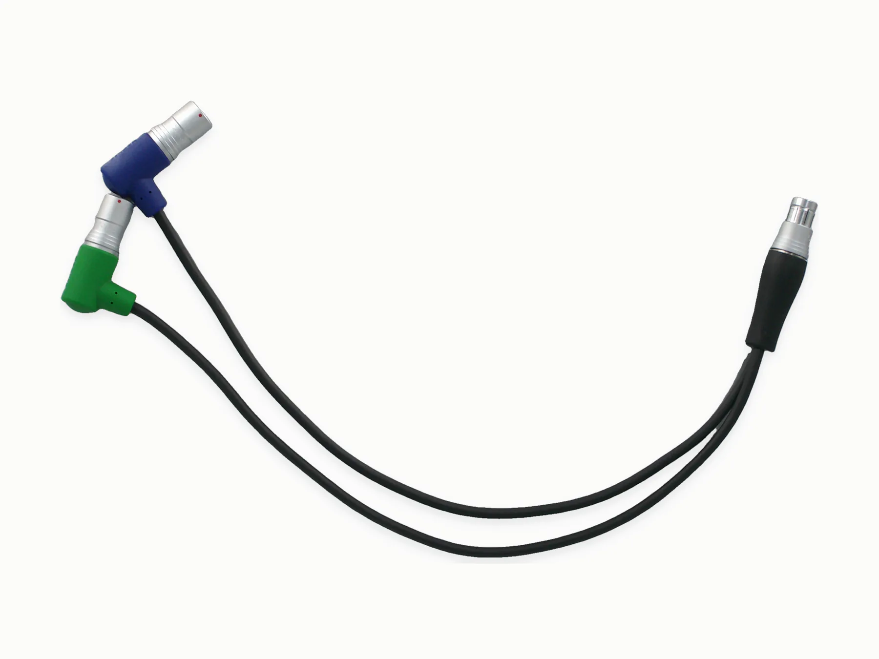
Black multi-branch cable with blue, green, and black connector ends and the branch route visible.

Cable constructions and molded components

Multi-branch connector cable

Black multi-branch cable with blue, green, and black connector ends and the branch route visible.

Market / context
Project-specific
Equipment end
Right-angle connector ends
Discuss this molded construction

Insert preparation, molding, and trimming

  1. 1Wire cutting
  2. 2Wire stripping
  3. 3Terminal crimping
  4. 4Soldering
  5. 5Vertical overmolding / insert molding
  6. 6Electrical testing

Wiring, dimensions, finish, and specified sealing checks

  • Inspect molded envelope, cable exit, flash, surface finish, color, and marking against the drawing or sample.
  • Check continuity, polarity, and connector seating after insert molding and trimming.
  • Run sealing, pull, or validation tests when the target level, fixture, and pass/fail limits are supplied.

New tooling, mixed diameters, sealing targets

Sealing, IP, airtightness, or waterproof expectations

3D overmold geometry and material hardness

Mixed cable diameters in the same molded cavity

Qualified-supplier coordination

  • Horizontally injection-molded housings requiring horizontal molding machines
  • PCB assemblies / circuit boards
  • Specified plug, connector, or component sourcing

For quotation

A drawing or 3D view is more useful than a long description

  • Connector part numbers with drawing, sample, sketch, or 3D geometry
  • Cable exit, molded envelope, material hardness, color, and marking
  • Validation target for strain relief, sealing, pull, or durability when required

Request a quote

Send the overmold geometry

Include the connector and cable, exit direction, material preference, and any pull or sealing target. Tooling can then be checked against the shape.

Start an RFQ