
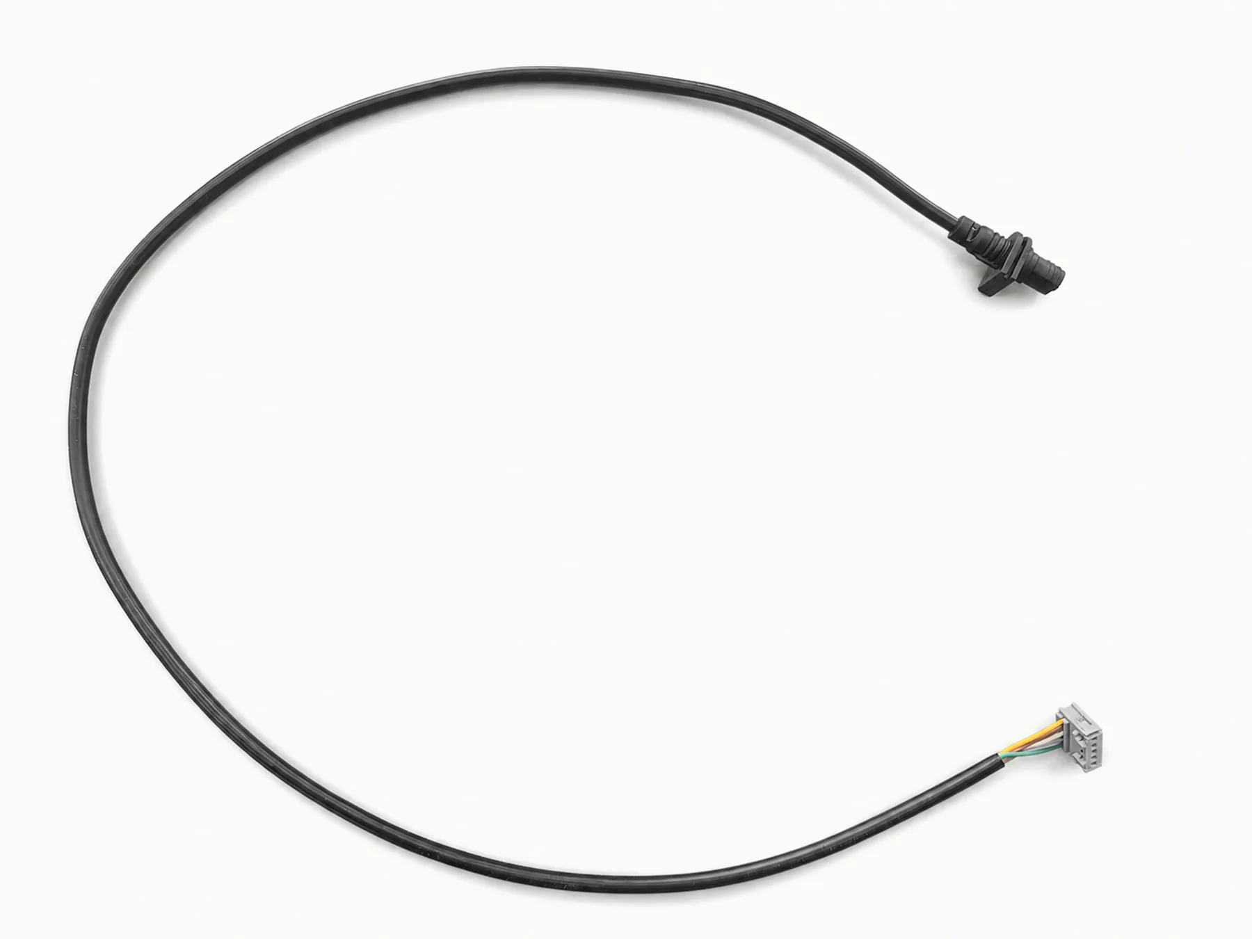
Connector and termination layouts
Long connectorized cable
Long black cable assembly with molded connector ends and the complete cable path visible.
- Market / context
- Project-specific
- Equipment end
- Molded connector end
IP67 Communication Cables
This product family combines IP67-sealed circular connector interfaces with molded cable exits and specified conductor or terminal ends. MTTJ prepares the cable and connector, terminates the wiring, molds the exit, and checks the finished route, pinout, and sealing requirements against the supplied build package.
Send Project Details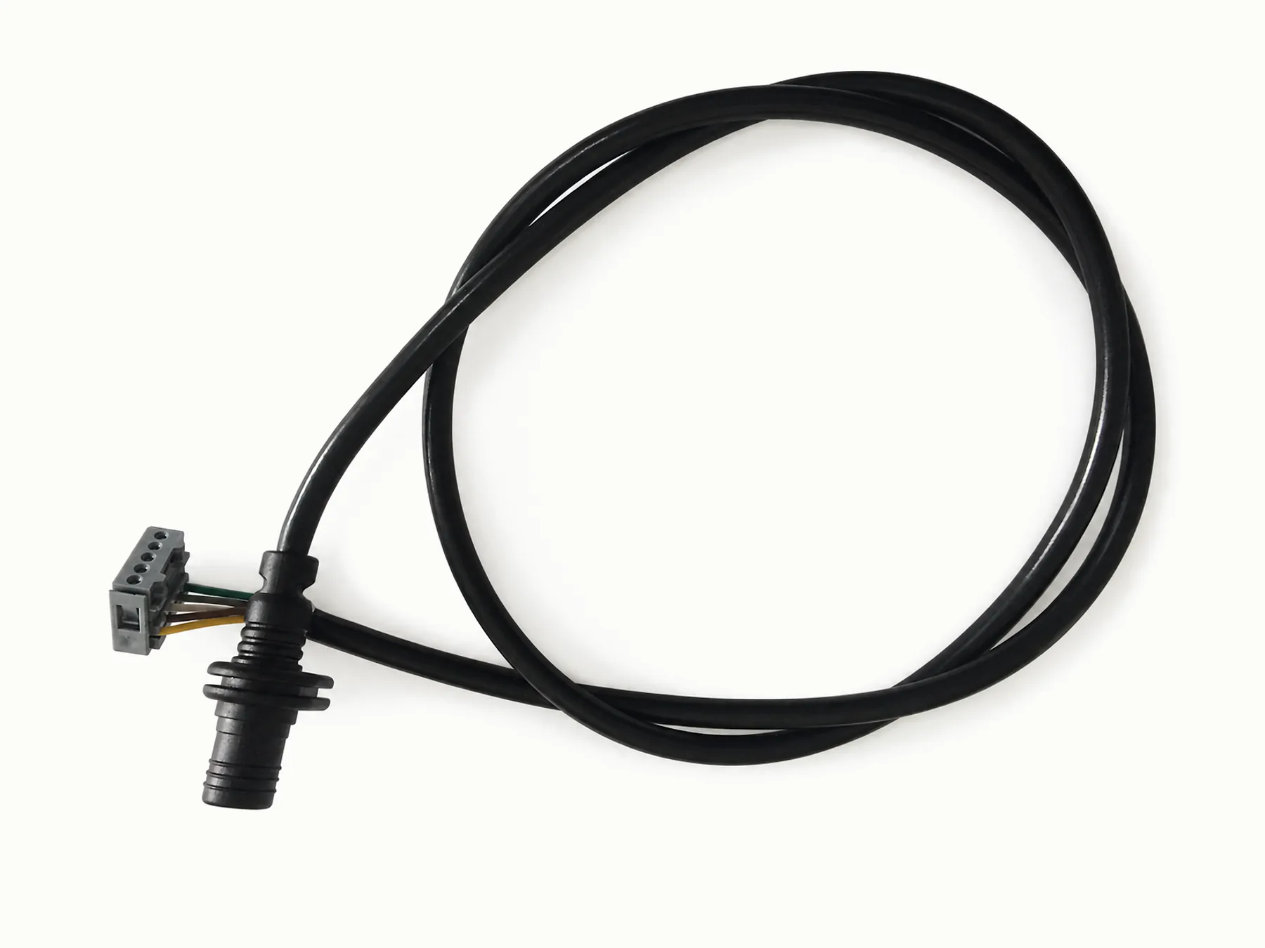
The assembly shows a circular connector, specified cable exit, and prepared conductors. Pinout, shield termination, and molded strain relief control the finished build.
Circular interface
Part number, mating orientation, pinout, cable construction, shield or ground termination, exit direction, and overmold geometry should be shown together.
| Connector interface | Connector part number, mating interface, pinout, and wiring diagram required |
|---|---|
| Overmold geometry | Drawing, 3D geometry, sample, or sketch sets the molded shape. |
| Cable exit | Straight, angled, or strain-relief exits should be shown on the connector drawing. |
| Shielding | Grounding and shield termination points should appear in the wiring plan. |
| Testing | Continuity, polarity, hi-pot, insulation, or functional checks follow the supplied method. |
Product range
These configurations show circular connector bodies, molded exits, conductor ends, terminal ends, and multi-component routes used in this sealed communication cable family.
Connector and termination layouts
Long black cable assembly with molded connector ends and the complete cable path visible.
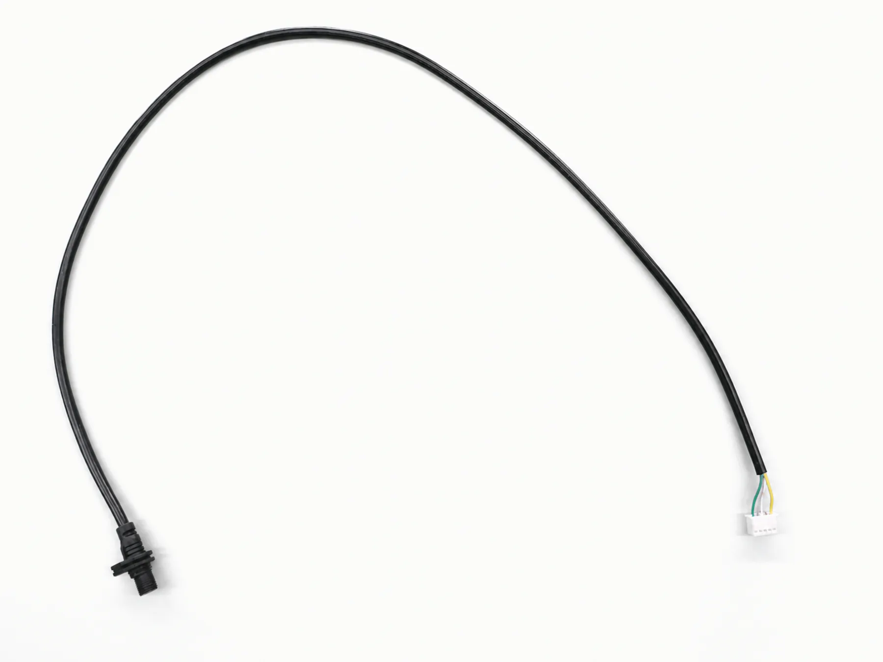
Connector and termination layouts
Compact black molded connector cable shown from above for route and connector-position review.
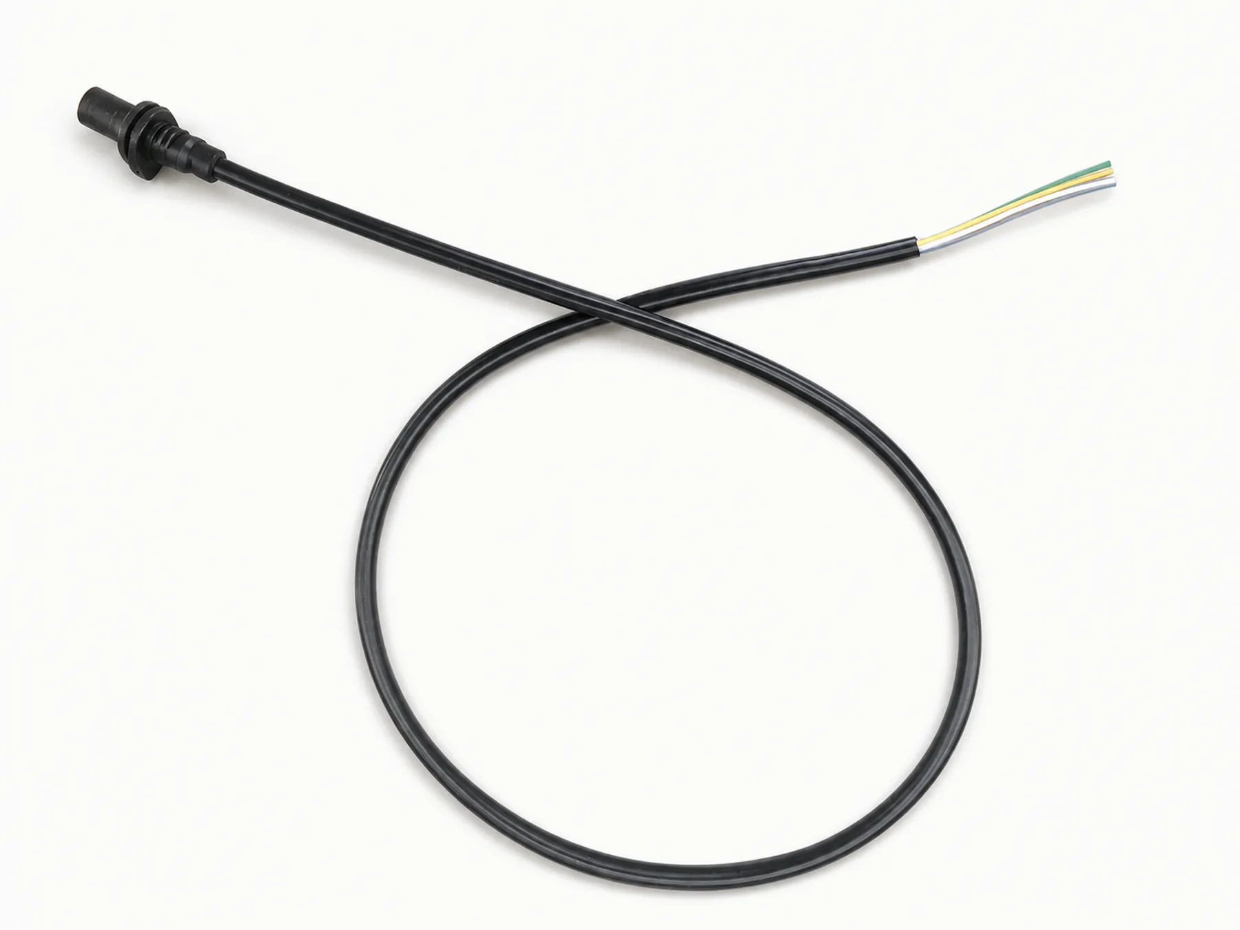
Connector and termination layouts
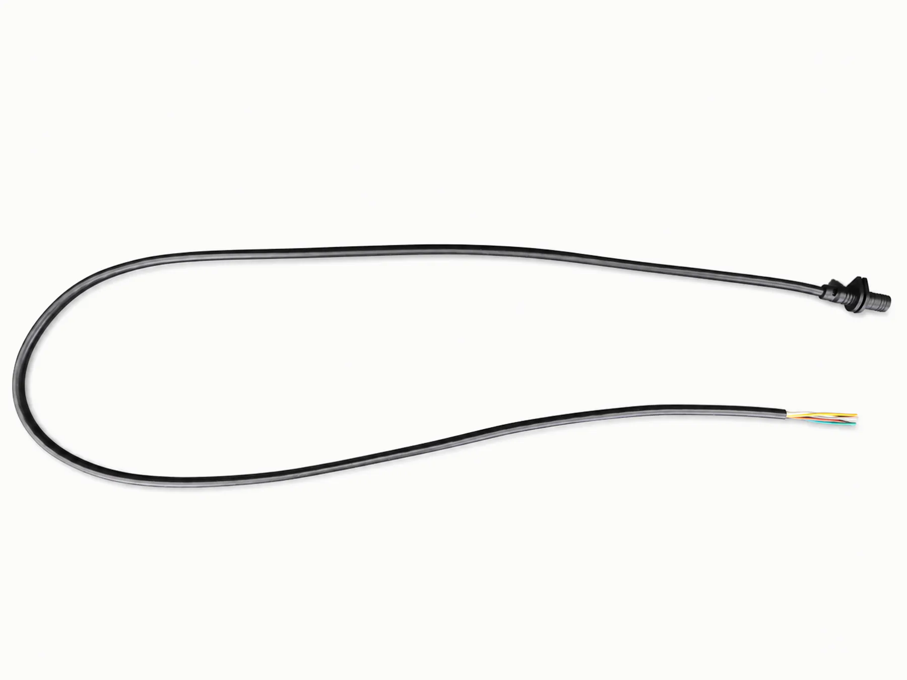
Long cable assembly with a molded connector and four colored conductors visible at the prepared end.
Connector and termination layouts
Looped molded connector cable with the conductor end and cable routing visible in one frame.
Connector and termination layouts
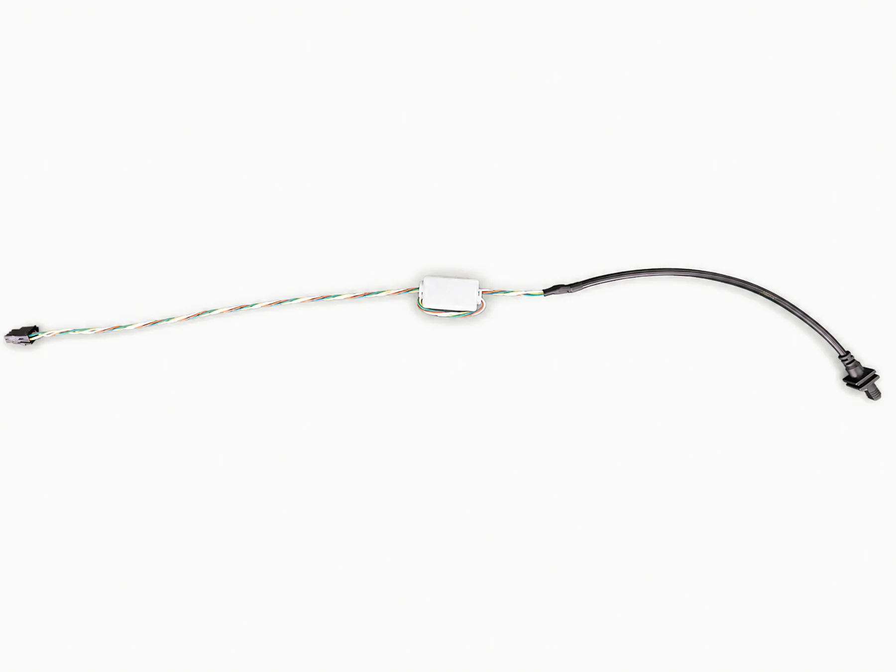
Cable assembly with several connector and molded component sections for multi-interface planning.
Connector and termination layouts
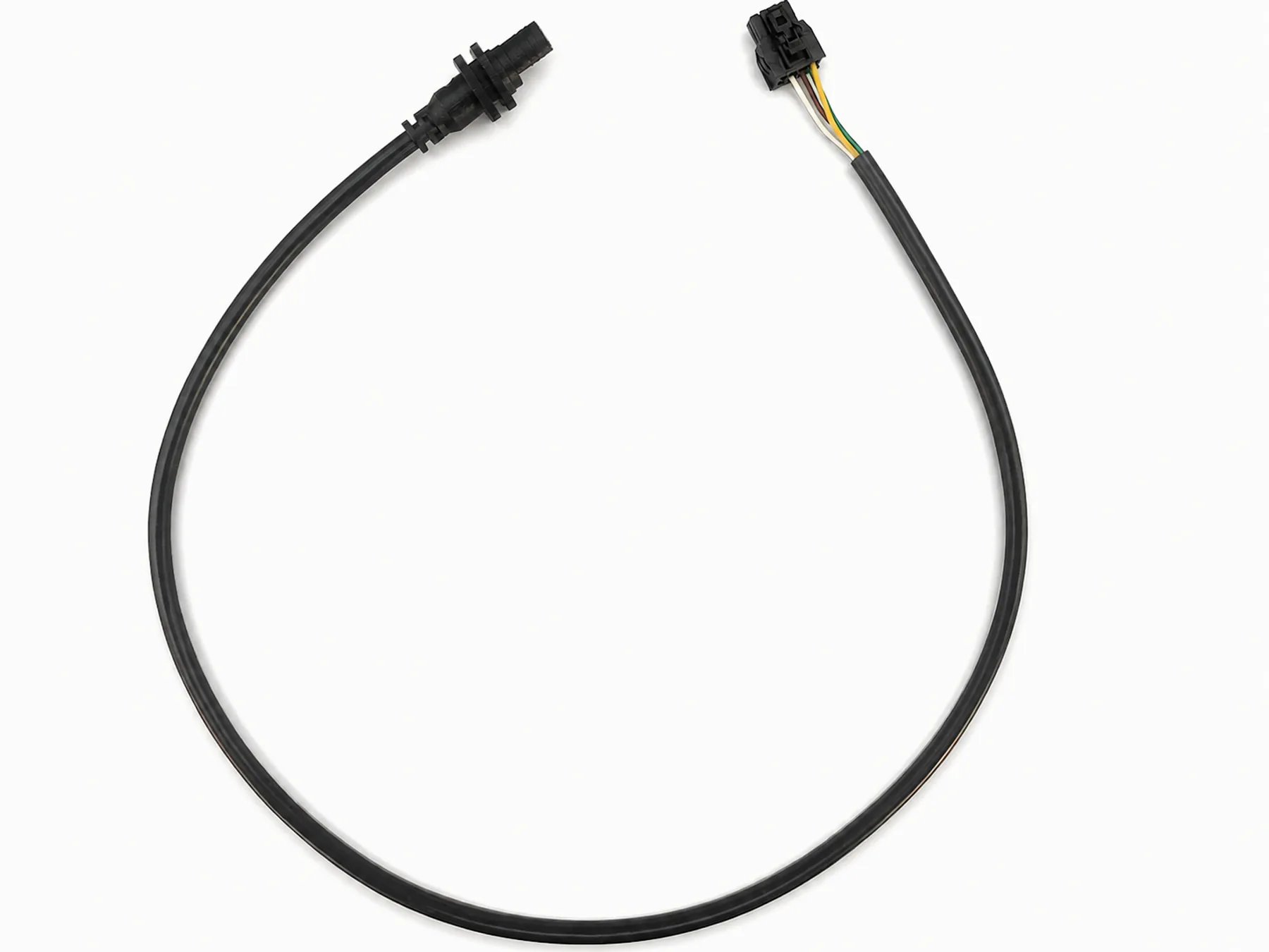
Looped molded connector cable showing the full route and terminal-end arrangement.
Connector pinout and mating interface
Shield termination and signal requirements
Sealing, IP, or airtightness expectations
For quotation
Related routes
Request a quote
Include the connector part number, mating orientation, pinout, shield treatment, cable construction, and overmold shape.