
Interconnect Cables
Custom Interconnect Cable Assemblies
Interconnect cables join specified points inside equipment or between subassemblies. MTTJ builds D-sub, circular-connector, pigtail, terminal-block, and other drawing-based assemblies with the specified pinout, shielding, labels, and checks.
Send Project Details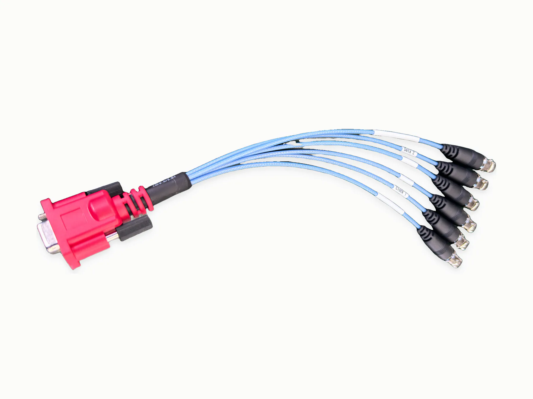
D-sub equipment interconnect cable
The assembly joins specified equipment points with connectorized ends. Pinout, cable length, shielding, labels, and mating orientation are the main build details.
Equipment-to-subassembly connections
- Internal equipment interconnects
- Control and display connections
- Security and electronic equipment
- Appliance and foodservice equipment
- OEM subassembly wiring
D-sub, circular, pigtail, terminal-block ends
- Connectorized cable ends
- Pigtails, D-sub style connectors, circular connectors, or terminal blocks
- Shielded or unshielded cable check
- Labels and wire markers
- Custom lengths and packaging
Cable, connector, shield, marker choices
- PVC
- PU / TPU
- TPE
- Specified shielded or unshielded cable
- Specified connectors
Connection baseline
Pinout, mating interfaces before length
The drawing should identify both connection points, connector part numbers, pinout, cable type, length, shielding, label positions, and the required checks.
| Cable function | The drawing should identify power, signal, data, or control use. |
|---|---|
| Connector type | Connector part numbers or accepted equivalents set the mating interface. |
| Shielding | Shield braid, foil, drain wire, and grounding points should appear on the drawing or schematic. |
| Cable routing | Length, bend area, strain relief, and labels decide how the interconnect is built. |
| Testing | Continuity, polarity, and functional checks follow the application and supplied test method. |
Examples
Product and process examples
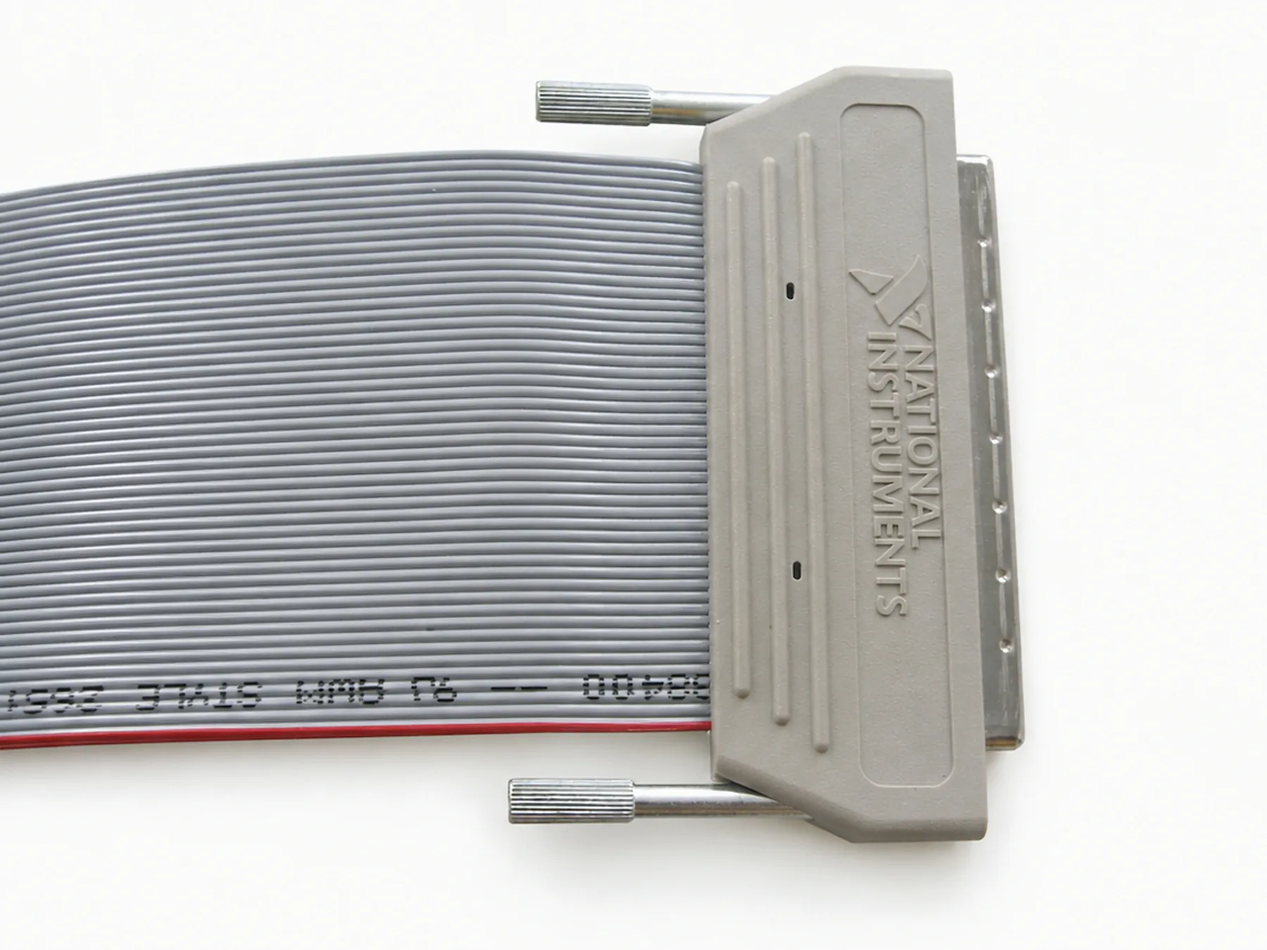
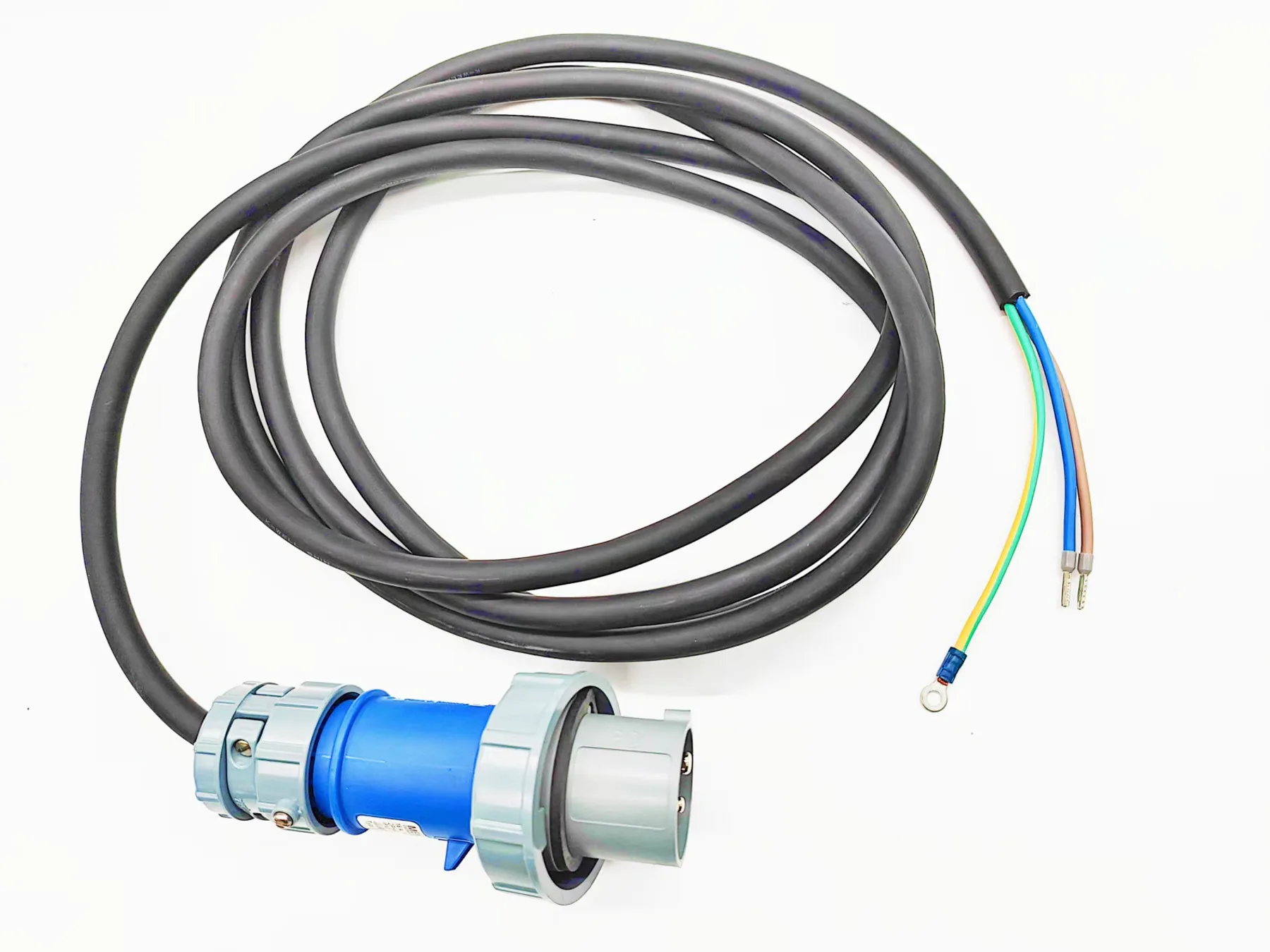
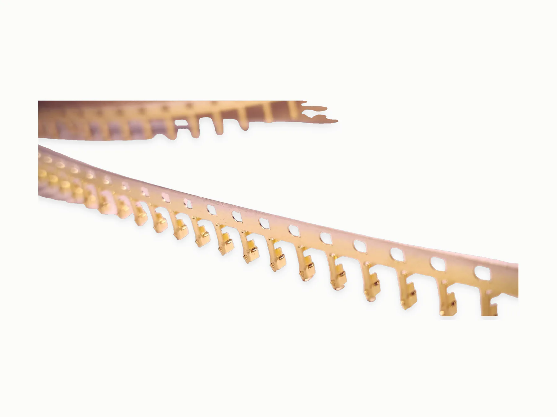
These images show visible assembly features. Quotation and production planning follow the supplied drawing, materials, tests, and record requirements.
Cable preparation, termination, labeling, assembly
- 1Wire cutting
- 2Wire stripping
- 3Terminal crimping
- 4Soldering
- 5Coaxial cable stripping
- 6Electrical testing
Mating fit, pinout, continuity, shield termination
- Check pinout, continuity, polarity, and mating fit between the named equipment connection points.
- Inspect cable length, label placement, shield termination, and strain relief against the drawing.
- Run functional, hi-pot, impedance, or signal checks when supplied the method and limits.
Signal performance, specified parts, records
Shielding, grounding, or signal integrity requirements
Specified connector substitution
Outdoor, UV, oil, or flexing environment
Qualified-supplier coordination
- Horizontally injection-molded housings requiring horizontal molding machines
- PCB assemblies / circuit boards
- Specified plug, connector, or component sourcing
For quotation
Show connection points, pinout
- Connection points, connector part numbers, pinout, and cable type
- Length, shielding or grounding plan, label rules, and application environment
- Continuity, functional, impedance, or other test method when required
Related routes
Continue with the closest product, capability, industry, or guide
Request a quote
Send interconnect drawings
Identify the mating connectors, pinout, cable construction, length, shielding, and any functional check tied to the equipment.