
Industrial Control Cable Assemblies
Industrial Control & Equipment Interconnect Cable Assemblies
Industrial control cables connect PLCs, sensors, displays, cabinets, and equipment interfaces where pinout, shielding, and grounding need to stay consistent. MTTJ builds the assembly to the control drawing or schematic and checks circuit identity, connector seating, labels, and shield termination.
Send Project Details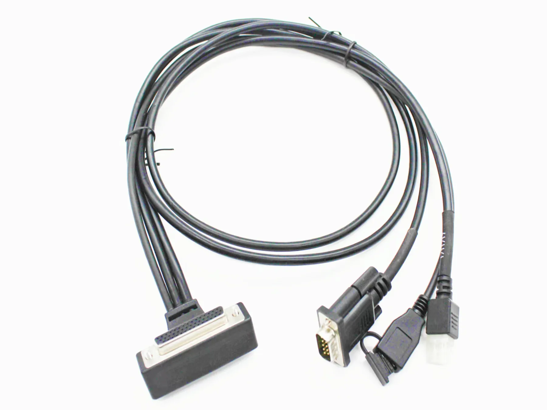
D-sub industrial control cable
The cable uses D-sub style connectors for control, display, sensor, or cabinet interfaces. Pinout, shielding, grounding, and labels follow the control drawing.
PLCs, sensors, displays, control cabinets
- Servo, encoder, and control cabinet connections
- PLC and machine interface wiring
- Automation equipment interconnects
- Display, access control, and power adapter internal wiring
- Custom equipment cable routing
Signal conductors, shielding, grounding, labels
- Multi-conductor control cables
- Shielded cable requirements
- Connectorized cable ends
- Labels and wire markers
- Overmolded strain relief when specified
Control cable, connector choices
- PVC
- PU / TPU
- TPE
- Specified shielded or unshielded control cable
Control circuit
Use the schematic for pinout and shielding
Connector part numbers, cable type, length, conductor count, shield termination, grounding points, labels, and functional checks should match the equipment schematic.
| Signal and control requirements | Conductor count, shielding, connector type, and environment set the control cable. |
|---|---|
| Shielding | The drawing should show shield type, drain wire, and grounding points. |
| Connector type | Connector part numbers or accepted equivalents set the mating interface. |
| Cable routing | Length, bend, strain relief, and labels determine the assembly layout. |
| Testing | Continuity, polarity, and functional checks follow the equipment test method. |
Examples
Product and process examples
These images show visible assembly features. Quotation and production planning follow the supplied drawing, materials, tests, and record requirements.
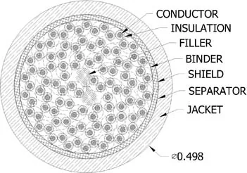
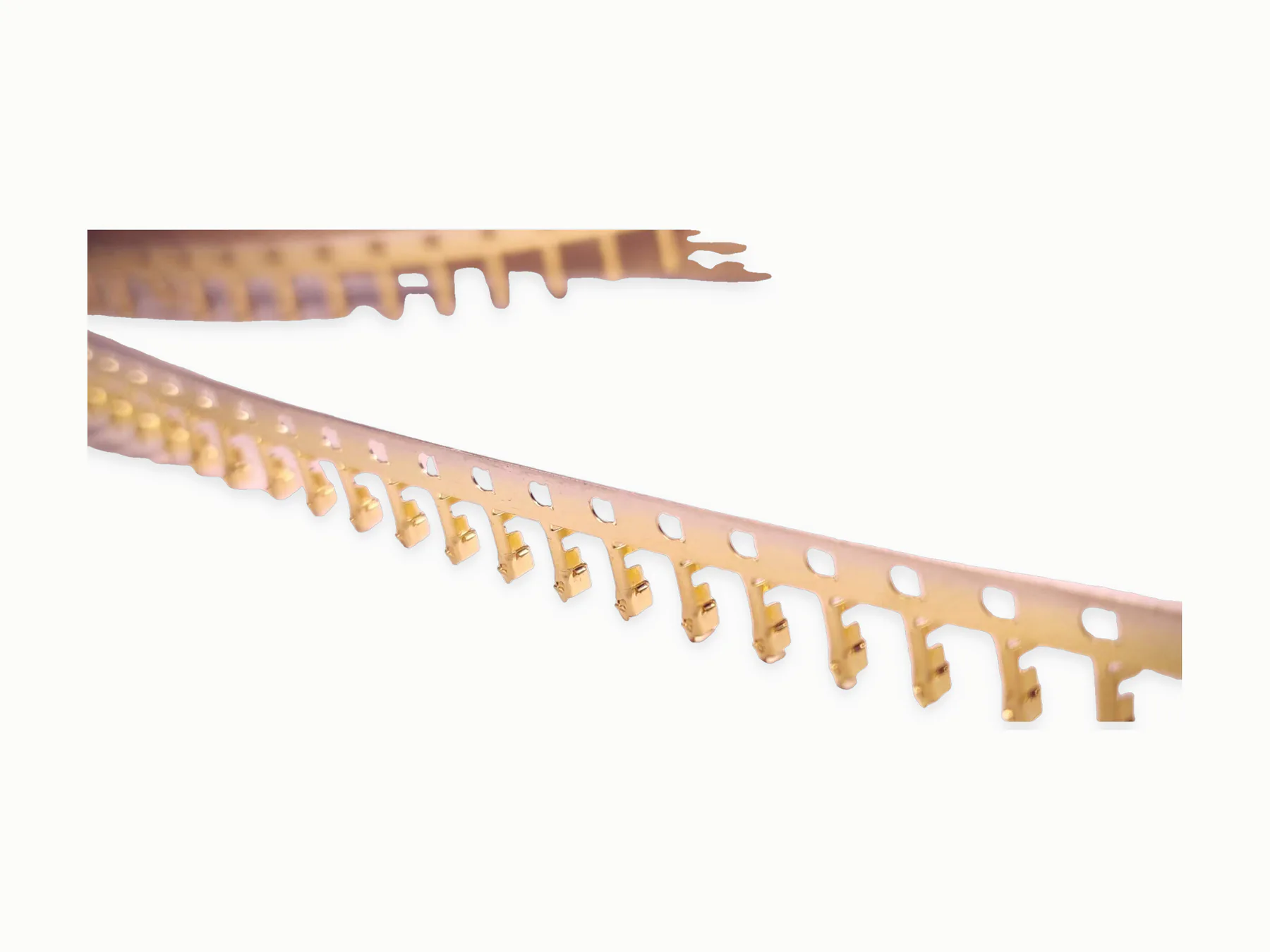
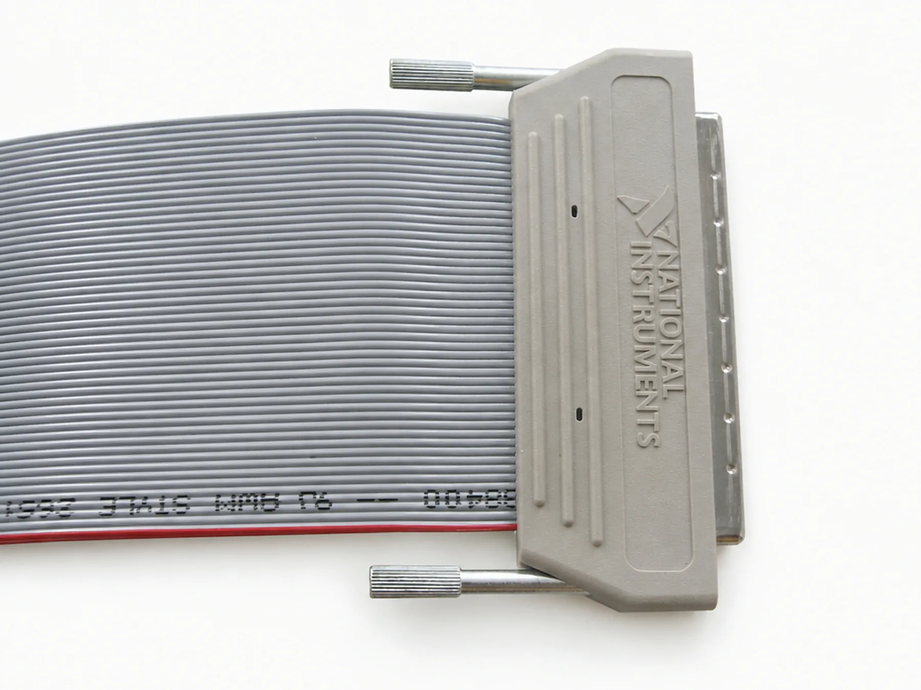
Cable preparation, termination, shield treatment, assembly
- 1Wire cutting
- 2Wire stripping
- 3Terminal crimping
- 4Soldering
- 5Coaxial cable stripping
- 6Electrical testing
Continuity, polarity, pinout, shielding, function
- Check continuity, polarity, pinout, and connector seating against the control schematic.
- Inspect shield termination, grounding points, labels, strain relief, and cable routing.
- Run functional, hi-pot, or signal checks when the equipment test procedure is supplied.
Movement, electrical noise, outdoor exposure
High-flex, drag-chain, or repeated motion use
Shielding and grounding scheme
Outdoor, IP, UV, oil, or temperature requirements
Qualified-supplier coordination
- Horizontally injection-molded housings requiring horizontal molding machines
- PCB assemblies / circuit boards
- Specified plug, connector, or component sourcing
For quotation
Send control schematic, interface details
- Control drawing or schematic with connector part numbers and pinout
- Cable type, length, conductor count, shielding, grounding, and labels
- Functional, signal, continuity, or final inspection method
Related routes
Continue with the closest product, capability, industry, or guide
Request a quote
Send control-cable drawings
Identify the connectors, pinout, cable construction, shield and ground treatment, length, and equipment test to be used.