Design & Materials
Cable Shielding and Grounding RFQ Guide
Shielding only works as specified when the cable construction, drain wire, connector termination, grounding point, and test method are defined together. The RFQ should show where the shield starts, ends, and connects.
Prepared by MTTJPublished: Updated:
Decision summary
What to carry into the decision
- Define shield type, coverage or construction, drain wire, and termination at each end.
- Show where the shield connects to shell, pin, chassis, PCB, or remains isolated.
- Tie signal or noise expectations to the equipment test method instead of assuming a shield construction guarantees performance.
Direct answer
A shielded cable RFQ should define the shield type, coverage target if specified, drain wire, grounding point, connector termination, jacket, and test method. Document the shield termination in the drawing or wiring table.
Shielding inputs
The routing and equipment interface decide how much shielding information is needed.
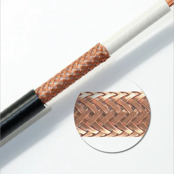
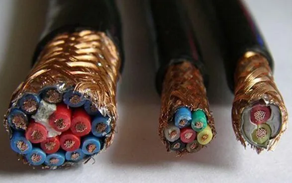
- Cable construction with braid, foil, drain wire, separator, filler, and jacket details when specified.
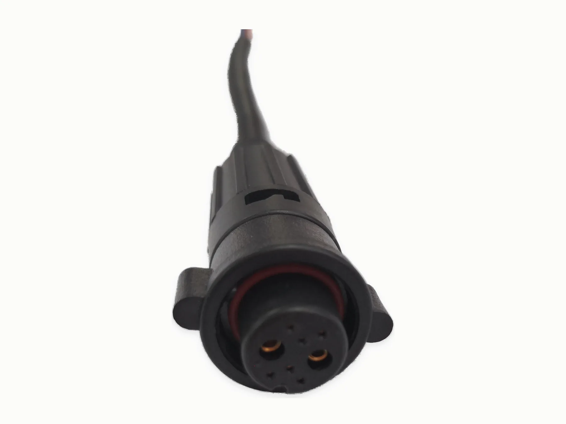
- Connector pinout, shell connection, ground point, one-end or both-end shield termination, and label notes.
- Signal type, impedance or low-noise expectation, continuity, functional, hi-pot, or other test method.
- Routing environment, bend radius, motion, temperature, moisture, oil, UV, and packing needs.
RFQ table
Use one table row for each shielded cable or branch when a harness has mixed functions.
| Shield start/end | Where the shield begins, where it ends, and whether it is cut back or carried through. |
|---|---|
| Grounding | Ground point, connector shell, drain wire termination, or floating requirement. |
| Verification | Continuity, resistance, functional, impedance, or inspection method supplied by the project. |
Define performance and verification
State EMC, impedance, certification, or application requirements with the cable construction, grounding plan, test method, acceptance limits, and required documents.
Shield termination table
Describe each end independently.
| Cable construction | Foil, braid, combination, drain wire, jacket, and any coverage or overlap requirement. |
|---|---|
| End A | Connector shell, pin, pigtail, chassis, insulation, or isolated treatment. |
| End B | Connector shell, pin, pigtail, chassis, insulation, or isolated treatment. |
| Verification | Continuity path, resistance, isolation, signal or impedance method, fixture, and limits. |
Common grounding ambiguities
A schematic symbol may not show the physical termination. Add section views or work notes for braid trim length, drain-wire path, shell contact, pigtail length, insulation, and the point from which each dimension is measured.