Design & Materials
Wire Harness Connectors and Terminals Guide
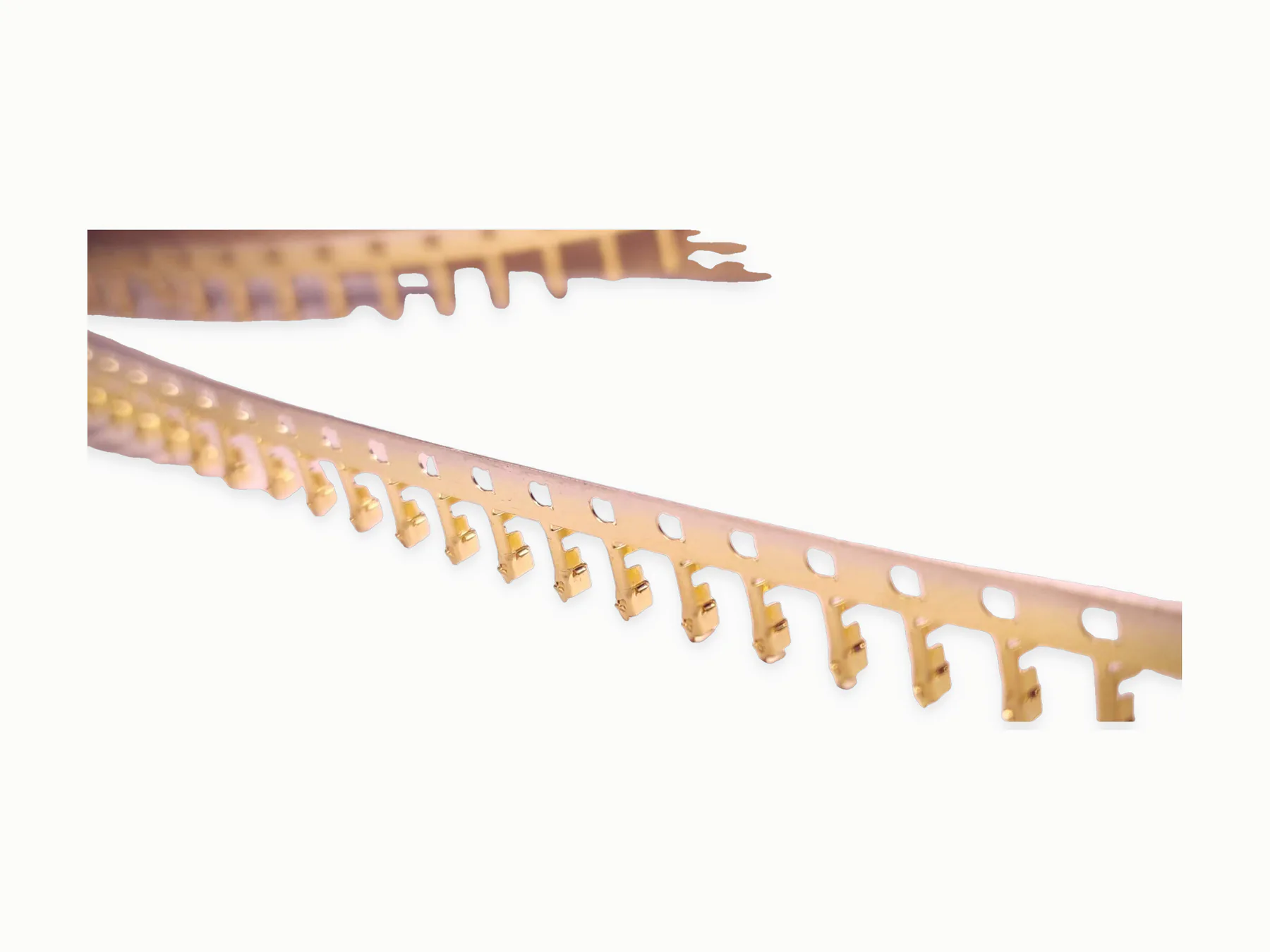
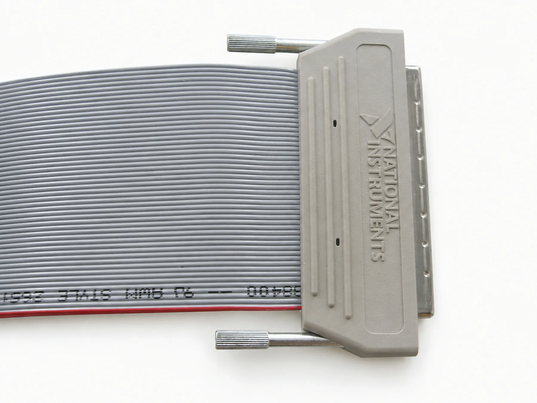
Connector and terminal choices determine fit, crimp method, wire range, tooling, sealing, labels, inspection, and records. When an inquiry specifies Hirose, TE, Molex, JST, Amphenol, Harting, or Fischer, include the applicable family or part number, sourcing requirements, and substitution rules.
Prepared by MTTJPublished: Updated:
Decision summary
What to carry into the decision
- Record connector housing, terminal, seal, lock, keying, and mating information as separate BOM lines.
- Match terminal and seal data to wire size, insulation diameter, and approved applicator information.
- Treat an equivalent as a controlled proposal, not as permission to substitute any compatible-looking part.
Direct answer
List connector housings, terminals, seals, backshells, locks, and project-approved substitution rules in the BOM. Hirose, TE, Molex, JST, Amphenol, Harting, and Fischer may be discussed when the project specifies the applicable family or part. Include the matching wire range, strip length, crimp data, pull-force requirements, and visual inspection criteria when supplied.
Connector and terminal RFQ table
A small amount of connector data can prevent major sourcing or tooling changes later.
| Connector | Part number, mating part, orientation, lock, seal, keying, and no-substitution note. |
|---|---|
| Terminal | Part number, wire gauge range, crimp height or supplier data, strip length, and pull test criteria. |
| Inspection | Visual limits, seating check, continuity, polarity, and functional or fit checks when required. |
Checklist before release
Before approving a harness build, confirm the connector package is complete.
- Connector and terminal part numbers match the latest drawing and BOM.
- Equivalent components are clearly allowed or clearly prohibited.
- Crimp, solder, seal, and assembly criteria are visible to production and inspection.
- Packing and label requirements do not conflict with connector protection needs.
Confirm component details
Use the supplied component data and RFQ to confirm brand, connector series, sourcing status, allowed equivalents, wire range, sealing requirements, required documents, and availability.
Connector data checklist
Keep the interface and termination data on the same controlled list.
| Housing | Manufacturer, full part number, keying, color, cavity count, and mating part. |
|---|---|
| Contacts | Terminal part number, plating, wire range, applicator or process data, and cavity assignment. |
| Accessories | Seals, wedges, locks, backshells, clips, caps, and strain-relief parts. |
| Verification | Pinout, orientation, seating, pull or retention, continuity, polarity, and fit method. |
Prevent part-number drift
Do not rely on shortened distributor descriptions or photos. Carry the complete part number from BOM through purchasing, receiving, production, inspection, and change records, and record any authorized equivalent as a separate controlled item.