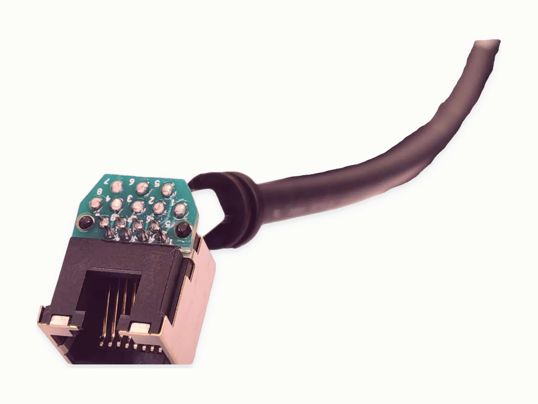
Manufacturing, Testing & Quality
Soldering, Crimping, and Terminal Inspection Guide
Soldering and crimping quality depends on wire preparation, terminal data, strip length, crimp height, solder criteria, connector seating, pull checks, visual inspection, electrical tests, and record requirements supplied with the project.
Prepared by MTTJPublished: Updated:
Decision summary
What to carry into the decision
- Match terminal, wire, applicator or process data, strip length, and inspection criteria before production.
- Use measurable crimp, pull, seating, solder, visual, and electrical criteria where they are required.
- Record inspection frequency and traceability separately from the acceptance method.
Direct answer
Include wire type, gauge, strip length, terminal data, crimp criteria, solder criteria, connector seating, pull-force requirements, visual limits, electrical test method, and record format in the RFQ when soldering or crimping is critical.
Inspection table
Inspection should follow the component data, drawing, and project requirements.
| Wire preparation | Cut length, strip length, nicking limits, tinning requirement, and exposed conductor length. |
|---|---|
| Crimping | Terminal data, applicator, crimp height, pull force, bell mouth, insulation support, and visual limits. |
| Soldering | Solder joint criteria, heat limits, strain relief, cleaning, board handling, and electrical checks. |
| Records | Inspection report, pull-check record, test result, lot record, or shipment record when requested. |
RFQ checklist
Supply the details that production and inspection need before build planning.
- Terminal or connector part numbers and supplier data.
- Wire gauge, insulation, conductor type, strip length, crimp or solder method, and accepted equivalents.
- Pull-force, continuity, polarity, functional, hi-pot, visual, or dimensional test criteria.
- Sample plan, inspection frequency, record format, packing, and delivery destination.
Set inspection criteria
Set terminal and soldering inspection criteria from the drawing, component data, supplied inspection standard, or project test method.
Termination inspection matrix
Tie the method to the exact component and wire combination.
| Preparation | Cut and strip length, conductor damage limit, strand condition, tinning if specified, and exposed conductor. |
|---|---|
| Crimp | Terminal, wire range, applicator, crimp dimensions, bellmouth, conductor and insulation support, and pull check. |
| Solder | Joint form, wetting or coverage criteria, heat and handling limits, cleaning, support, and visual method. |
| Assembly record | Connector seating, lock position, cavity check, electrical result, frequency, lot or unit ID, and disposition. |
Common inspection errors
A generic good-crimp photo cannot replace component-specific data. Avoid mixing terminal families, wire constructions, applicators, or pull methods in one limit without a controlled source that supports the combination.