
Beverage Equipment Cable Assemblies
Beverage Machine Valve Cable Assemblies
These short leads connect valves, controls, and internal wiring inside beverage and foodservice equipment. Builds can include crimped or soldered terminations, labels, optional overmolding, and electrical checks tied to the equipment drawing.
Send Project Details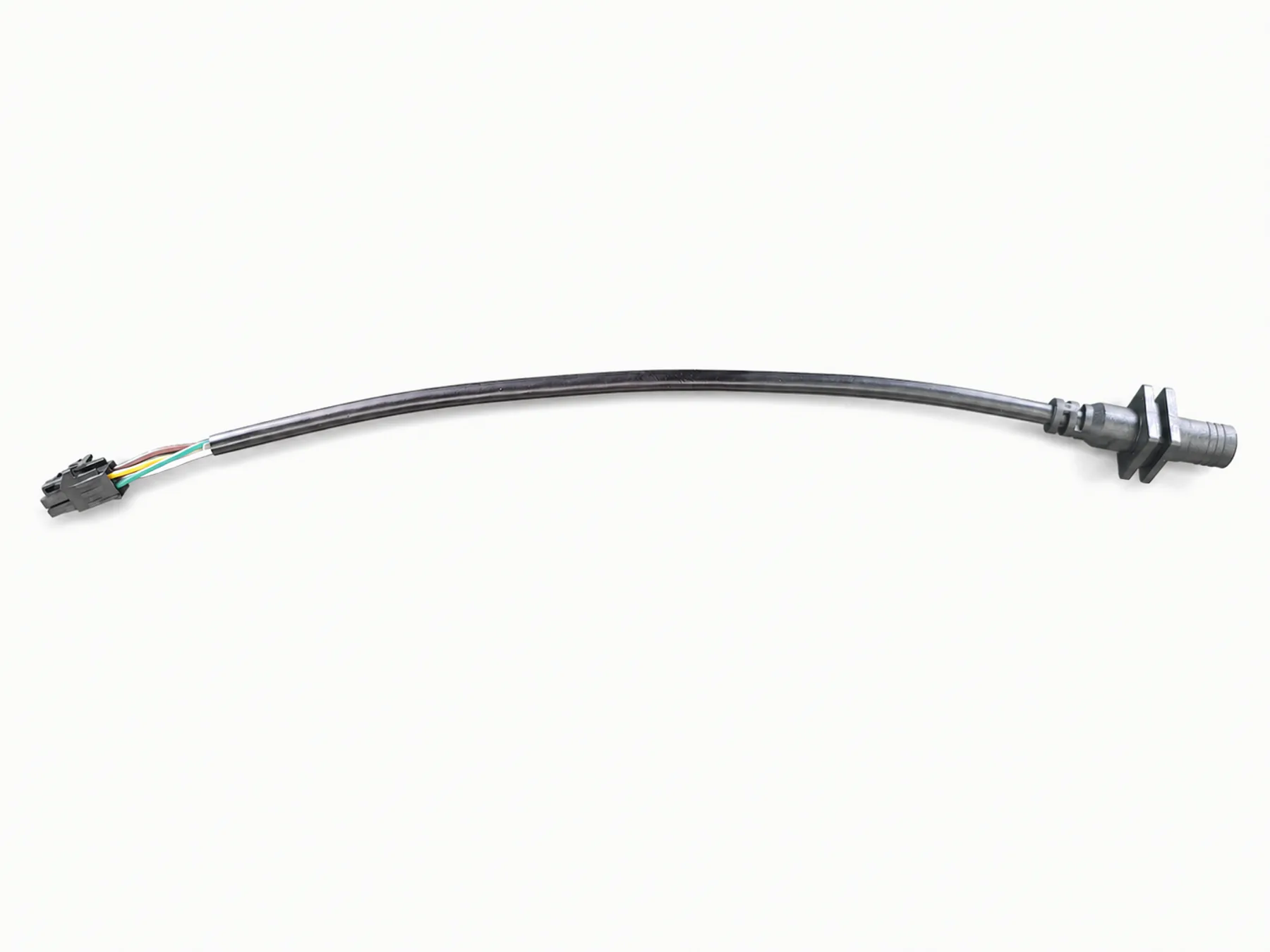
Short terminal-to-molded-connector lead
The image shows a short black cable with a white terminal housing at one end and a molded connector at the other.
Valves, controls, internal equipment wiring
- Commercial beverage equipment
- Foodservice dispensing equipment
- Valve control and internal equipment wiring
- Kitchen equipment subassemblies
- Specified equipment interconnects
Connectorized, stripped, labeled ends
- Valve lead assemblies
- Connectorized control cables
- Molded strain relief when specified
- Moisture and temperature material check
- Labels and packaging from the equipment or shipment instructions
Wire/jacket choices for heat, moisture
- PVC
- PU / TPU
- Silicone where specified
- Specified terminals and connectors
Equipment interface
Match leads to valve space
Connector type, wire gauge, length, routing space, temperature, moisture, and cleaning exposure affect the cable and end treatment.
| Valve interface | Connector, terminal, wire gauge, and equipment drawing set the valve lead. |
|---|---|
| Moisture exposure | Installation location and sealing target decide whether a moisture test is needed. |
| Temperature | Operating temperature comes from the equipment environment. |
| Material documents | The material name and document type determine what can be checked. |
| Testing | Continuity, hi-pot, insulation, or functional tests follow the specified method. |
Examples
Product and process examples
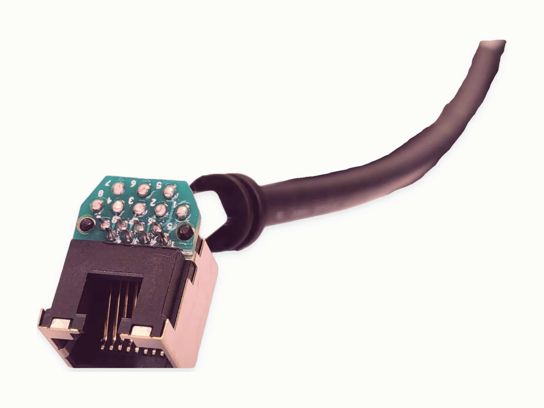
These images show visible assembly features. Quotation and production planning follow the supplied drawing, materials, tests, and record requirements.
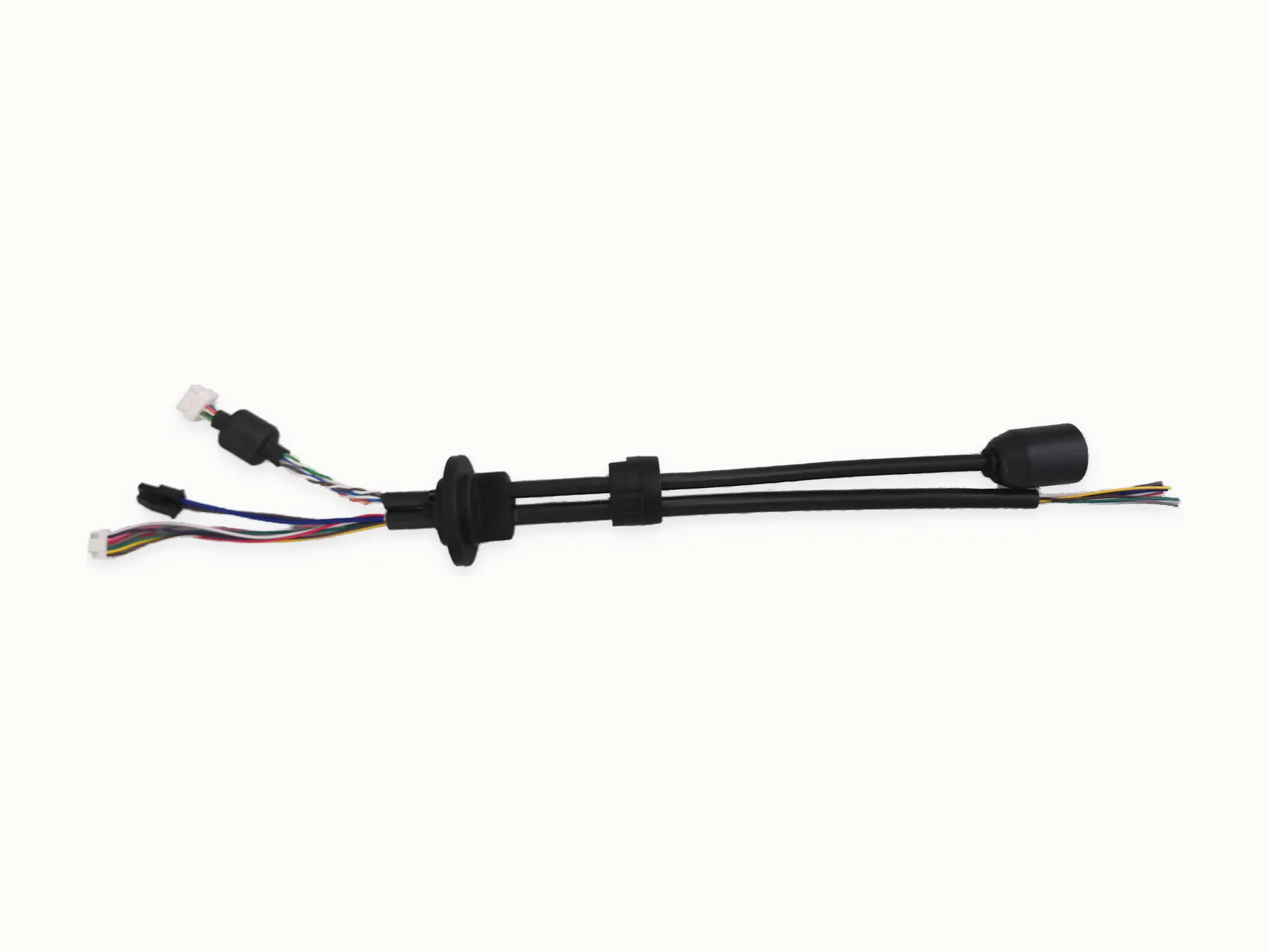
Cutting, termination, labeling, overmolding
- 1Wire cutting
- 2Wire stripping
- 3Terminal crimping
- 4Soldering
- 5Assembly
- 6Electrical testing
Continuity, polarity, fit, visual checks
- Check continuity, polarity, and valve connector fit against the equipment drawing.
- Inspect labels, lead length, stripped ends, solder or crimp points, and optional molded strain relief.
- Run hi-pot, insulation, moisture, or functional checks when the equipment program supplies the method and limits.
Moisture, temperature, material documents
Material exposure or high-temperature requirements
Moisture or IP-level expectations
Specified valve connector and test procedure
Qualified-supplier coordination
- Horizontally injection-molded housings requiring horizontal molding machines
- PCB assemblies / circuit boards
- Specified plug, connector, or component sourcing
For quotation
Show valve interface, cable route
- Valve connector or terminal model with wire gauge and cable length
- Moisture, heat, cleaning, or material details that affect the lead
- Test method, required records, quantity, and delivery destination
Related routes
Continue with the closest product, capability, industry, or guide
Request a quote
Send the equipment drawing or sample
Identify the connector, lead length, wire size, and operating environment. Add only the electrical or functional checks required by the equipment.