Design & Materials
Overmolded Cable Assembly Design Considerations
Overmolded parts are easiest to quote when the connector, cable exit, molded envelope, material hardness, marking, tooling assumptions, and validation method are shown together.
Prepared by MTTJPublished: Updated:
Decision summary
What to carry into the decision
- Freeze connector position, cable exit, molded envelope, material, and marking together.
- Tie sealing, pull, or flex expectations to a named method and measurable limit.
- Separate reusable tooling assumptions from dimensions that are still open during sample work.
Geometry drives the tooling discussion
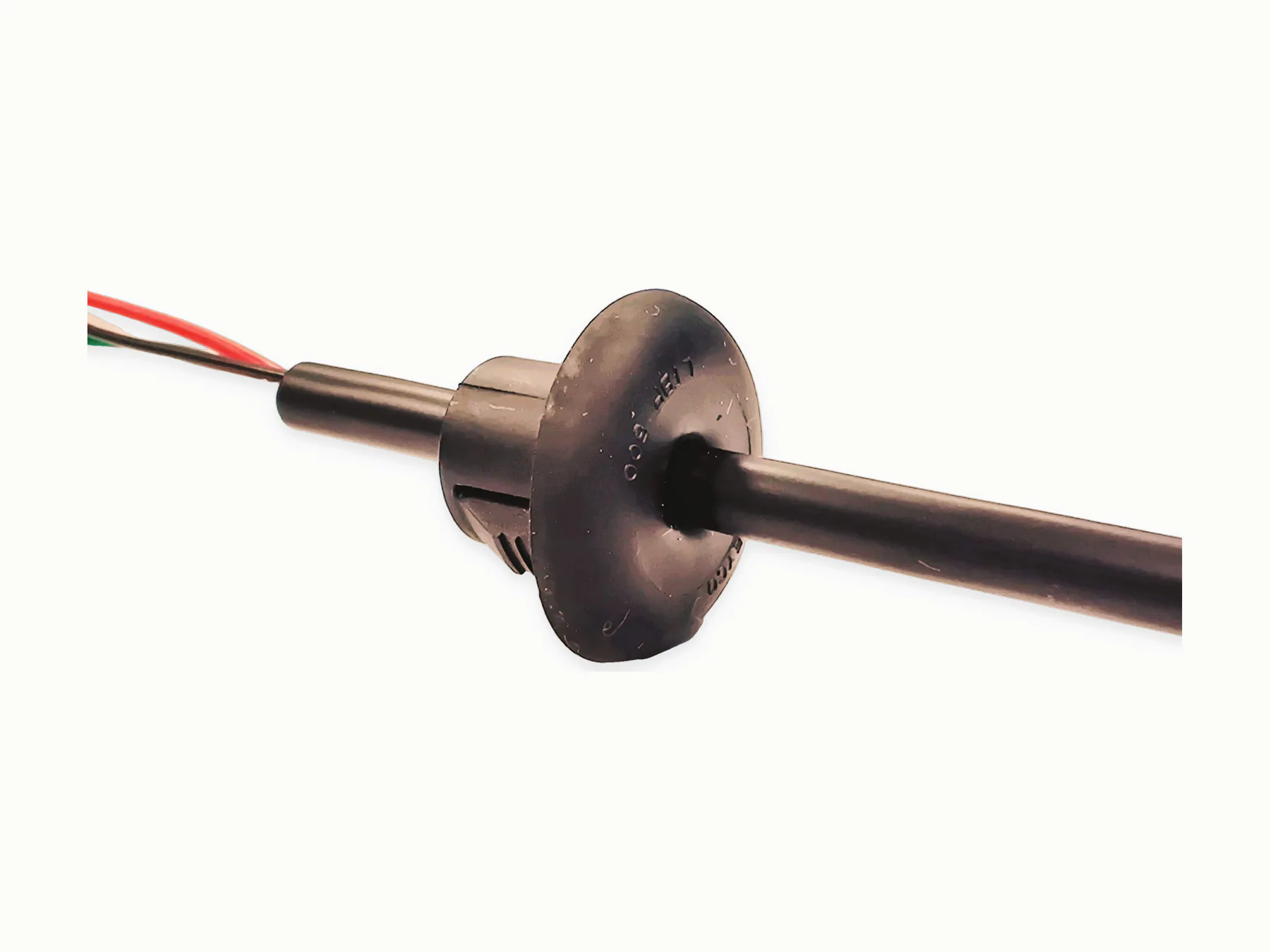
Name the connector, cable exit angle, strain relief length, molded envelope, color, marking, and any breakout, stop, gland, Y junction, or T junction feature in one drawing package.
A sketch can start the discussion; repeatable production needs a drawing, sample, or 3D geometry that fixes the molded shape.
When several cable diameters or exits share one molded feature, call out the critical sections so tooling and inspection use the same geometry.
Material choice affects durability and feel
PVC, PU, TPU, TPE, TPEE, TPV, and silicone may be considered depending on flexibility, sealing, handling, temperature, cleaning, and specified material needs.
Material hardness, surface finish, color, and marking should be discussed early when the molded section is handled by an operator or routed through a tight space.
Testing should match the application
Overmolded assemblies usually need continuity or polarity testing plus visual inspection of molded geometry, cable exit, flash, and surface finish.
For sealing or mechanical-validation targets, include the IP level, fixture, pressure or motion condition, test method, and pass/fail criteria.
Required records and component documentation for production planning
Overmolding is easier to quote when the project specifies the connector, cable exit, molded envelope, material hardness, marking, tooling requirements, and validation method together.
Material documents apply to the supplied material and stated scope.
Overmold decision table
Set each input before committing to a sample or tool concept.
| Interface | Connector identity, mating direction, keep-out zones, and insert position. |
|---|---|
| Cable exit | Cable outside diameter, exit angle, bend area, and strain-relief transition. |
| Molded body | Envelope, material or hardness preference, color, texture, and marking. |
| Validation | Visual, dimensional, pull, flex, sealing, or electrical method with limits. |
Common overmold mistakes
A generic sketch can hide the datum, cable tolerance, and connector keep-out zone. Another common error is asking one tool concept to cover different cable diameters without identifying the critical sections and inspection method.